|
|||||||||||||||||||||||||||||||||||||||||||||||||||||||||||||||||||||||||||||||||||||||||||||||||||||
|
|
Advanced HDL Stimulus Generation (Tutorial 4)This tutorial describes how to generate Verilog and VHDL stimulus files using WaveFormer Pro, VeriLogger Pro and TestBencher Pro. This tutorial is important because it describes exactly how the waveforms of a single timing diagram will be exported. It also covers advanced data types that are used in VHDL generation. TestBencher Pro customers should also work through the on-line TestBencher Tutorials, which cover the sample parameters that generate the self-testing code, and modifying the template files used to generate multi-diagram test benches. This tutorial covers how the following objects are exported into VHDL and Verilog:
1) Getting StartedGet a Full Version License If you are evaluating WaveFormer Pro, VeriLogger Pro or TestBencher Pro you need to upgrade the evaluation version by obtaining a 2 Week Trial License. This license will turn your evaluation version into a full version for 2 weeks. The instructions for obtaining a license are located in the evaluation directory under a file named 30day_Permanent License Request.rtf.
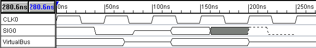
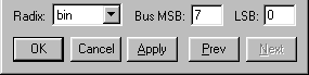
The first signal, CLK0 is a clock with a period of 50ns. The second signal, SIG0, is a waveform that contains all of the graphical states available in WaveFormer Pro. The third signal, VirtualBus, is a waveform drawn with valid and tristate segments. 2) Default Mappings: Hex and Binary TranslationsWaveFormer Pro supports a language independent bus format for hexadecimal and binary bus values. During the translation to Verilog or VHDL, the extended state value of a segment is evaluated to determine if it is a hexadecimal or binary number. If the extended state value begins with a 'b or 'h then it is assumed that the number is a binary or hexadecimal number and the number will be translated to the appropriate VHDL or Verilog bus value. If the extended state value does not start with 'b or 'h then the value is written out as it was entered, without any translation. To demonstrate the hex and binary translations, we will edit the signal VirtualBus so that it will correctly export as an 8-bit bus. We will also use the 'b and 'h values to set the segment values and compare how they export in VHDL and Verilog. Later in the tutorial we will generate the Verilog and VHDL code. Setting the size of a virtual bus to 8 bits:
Setting the values in a virtual bus waveform:
This behavior, of either translating the bus values or straight copying of the information is called the default mapping mode. WaveFormer Pro users can define additional mapping modes by editing the proper stimulus generation file, either verilog.epl, wvhdl.epl, or tvhdl.epl. These files will be discussed later in the tutorial. To use a new mapping mode, attach an object property to a signal called VhdlMapping or VerilogMapping with a value that is the name of the desired mapping mode routine. TestBencher Pro users will need to edit different files that are discussed in the TestBencher tutorial, but the editing and subsequent use is the same. 3) Generating Verilog CodeNext we will demonstrate how to generate Verilog stimulus vectors from timing diagrams.
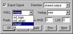
Look at the resulting file by clicking on the test.v tab on the bottom of the Report window. Notice how CLK0 uses a while loop to produce its transitions and how SIG0 uses assignment statements. Also note, values for the VirtualBus assignments have a 8’ in front which indicates that VirtualBus is an 8-bit vector. The first segment of VirtualBus has a value of, 8’b11101110, which is the correct Verilog syntax for an 8-bit bus with a binary value of 'b11101110. The next segment has a value of 8’bzzzzzzzz which is the value for an 8-bit tri-stated bus. Next value is 8’b00001010 which is a zero padded translation of the hexadecimal value 'hA. WaveFormer performs the Verilog stimulus generation using verilog.epl, which is located in the same directory as the main executable. View verilog.epl by selecting the Report > Open Report Tab menu option. Look at the %ToState array. This array determines how the different graphical waveform states are converted to Verilog (SIG0 demonstrates the results of this subroutine). You can modify the Perl script to perform the Verilog export to exactly your needs. When you are done viewing the verilog.epl file, close it with the Report > Close Report Tab menu option. Note: The weak high and weak low signals are not supported by some Verilog simulators. You may wish to map these values to 1 and 0 strong values. 4) VHDL - Advanced Data TypesWaveFormer Pro supports both simple std_logic signals and complex user-defined data types for VHDL test benches. By default all signals are assumed to have a type of std_logic and a direction of out (CLK0, SIG0, and VirtualBus will use the defaults for this tutorial). In this section you will add SIG1 and SIG2 to demonstrate signals with a standard integer type and a user defined type. Add SIG1 and SIG2
Change the type of SIG1 to integer and the type of SIG2 to MyColor.
Add Extended State information to the waveforms of SIG1.
Add Extended State information to the waveforms of SIG2.
Your timing diagram should resemble the figure below.
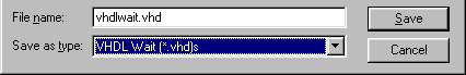
5) Exporting to VHDLIn VHDL there are two ways to write stimulus vectors: using wait statements or using transport statements. Transport-based test benches are smaller and easier to read than wait-based test benches, but wait-based test benches are easier to understand when single-stepping through a simulation to debug it. WaveFormer Pro ships with two different VHDL scripts to create both types of stimulus. Next, we will export the timing diagram to two different VHDL test benches. Export to a transport stimulus file:
Export to wait stimulus file:
View the file VHDLtran.vhd inside the Report window. Notice the entity and architecture structures and the types of all the signals. CLK0 uses a while loop to calculate its value. SIG0 shows how the graphical states are exported. VirtualBus is defined as an 8-bit logic vector. The state values displayed in the report window are in hexadecimal value, therefore ’b11101110 is translated as x"EE", "ZZZZZZZZ" after 70ns and ’hA is translated as x"0A" after 120ns, "ZZZZZZZZ"after 200ns. Also note that the tri-stated segments are also exported as 8-bit bus values. Like VirtualBus, SIG1 and SIG2 use extended state information to define the state values for their waveforms. However since their state values do not begin with 'b or 'h the information is used without making any changes to the data. Congratulations, you have now completed the HDL stimulus generation tutorial. If you have purchased TestBencher Pro, you should read the on-line TestBencher Pro tutorial on generating test benches, otherwise skip to the Advanced Simulation and Modeling tutorial. |

 at the top of the window to open the Edit Bus State dialog box. The Edit Bus State
dialog box can also be opened by double-clicking on the selected segment.
at the top of the window to open the Edit Bus State dialog box. The Edit Bus State
dialog box can also be opened by double-clicking on the selected segment. ) two times to advance to the next valid segment.
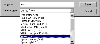

 button two times to add two signals.
 , and the second
click selects Valid as the toggle state
, and the second
click selects Valid as the toggle state
 (as indicated by the red
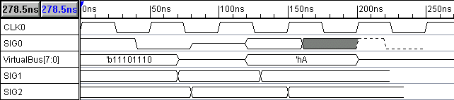
 button to
move to SIG2. Make sure that you moved to SIG2 and not to the previous VirtualBus
signal.
button to
move to SIG2. Make sure that you moved to SIG2 and not to the previous VirtualBus
signal.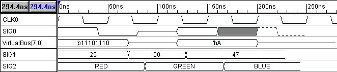
|
|