SimuTAG links FPGA chips to HDL Simulators
SimuTAG is a functional and real time verification system for FPGAs. Quickly find logic and synthesis
errors by comparing FPGA functional results against RTL model simulation results. Validate real time
FPGA results using Verilog and VHDL test benches.
SimuTAG is exceptionally easy to use because it makes use of the design files used to program the FPGA;
you never have to reenter mapping information. Using the JTAG pins of the Xilinx device SimuTAG links
the device directly to a VHDL or Verilog Simulator
- Facilitates IP CORE evaluation and validation of the available device on the board.
- Allows integrating the application modules around a component as a black box in VHDL
or Verilog.
- Functional verification and comparison against RTL results in simulation window.
- Capture real time data and display the data in a simulators waveform window.
- Interface to MATLAB and Simulink.
- Automatically generates necessary mapping files, given a VHDL or Verilog design file
and the BSDL (Boundary Scan description Language) file of the device.
Product Description
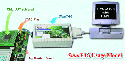
SimuTAG hooks directly up to a Windows based PC or a Sun machine that is running a VHDL or Verilog simulator.
SimuTAG Lite uses the parallel port and SimuTAG Pro uses a PCI board for the data transfer to the computer.
A JTAG cable connects SimuTAG to an application board where the Xilinx chip is socketed or soldered.
- Supports a variety of Xilinx devices that support INTEST instruction in JTAG.
- Supports VHDL and Verilog simulators with a PLI interface like VeriLogger Pro.
- Enables cycle-accurate design simulation.
- Exports vectors from simulator to the BSD cells of the device and imports the data from
the BSD cells of the device back to the simulator to facilitate visual analysis.
- Capture several seconds of real time data under the "Time Window Accumulate Mode".
Design Flow
SimuTAG is easy to use because it takes advantage of the design files that are used to develop and program
the FGPA. The basic design flow is as follows:
- Gather the following design files:
- The HDL file with the VHDL top entity or Verilog top module
- The EDIF file after synthesis using Leonardo Spectrum or Synplicity
- The PAD (Xilinx) file after Place & Route
- The verified BSDL file for the Device soldered /socketed to the board.
- Use the SimuTAG software to create the necessary mapping files for the Simulator.
- Power on the application board and have the Device configured.
- Connect the JTAG pins of SimuTAG unit to the Application board.
- Initialize the SimuTAG unit.
- Run your simulation (Refer SimuTAG User manual).
- Watch the chip results directly on the waveform display window of your simulator.
Xilinx Devices Supported
SimuTAG currently supports the following Xilinx FPGA and CPLD chips. New models and chips can be added
by request. Please contact SynpatiCAD for more information.
- FPGAs: Spartan-II family, Spartan-IIE, Virtex, Virtex E, Virtex-II, Virtex-II Pro
- CPLDs: 9500, 9500XL, 9500XV
Requirements
- Simulator:
- For Verilog Interface: VeriLogger Pro or another Verilog OVI compliant simulator with
full PLI support.
- For VHDL Interface: ModelSim VHDL or another VHDL simulator with a PLI interface
- Operating System:
- Windows NT4.0, 2K,
- Solaris
- SimuTAG Lite attaches to the parallel port of the PC.
- SimuTAG Pro ships with a PCI card that uses a PCI slot in the PC or Sun.
|