|
Version 11.0 Features
SynaptiCAD is proud to release version 11.0 of GigaWaveViewer, Timing Diagrammer Pro, WaveFormer Pro,
DataSheet Pro, BugHunter Pro, VeriLogger Pro, and TestBencher Pro. Below are some of the new features:
Universal Features (added to all timing diagram editor products):
New Parameter Features
- New curved arrows for delays, setups and holds. In addition to the traditional
"right-angle" appearance of Delays, Setups, and Holds, these parameters can also be displayed as a straight
line or a curved arrow for documentation purposes.

- Control the color background of unreferenced parameters using View > Show Unreferenced
Parms in Gray menu. By default it is checked, but if unchecked the color will be the same as regular
parameters.
- Hide or Show all the parameters on a particular signal by right-clicking on the signal
label and choosing either the Hide Parameters on Selected Signal(s) or the Show parameters on
Selected Signal(s) menu option from the context menu.
New Signal Features
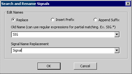
- The Search & Rename Signals dialog now supports the insertion of prefixes and
suffixes to signal names. And we have increased the speed of all the search and replace options
to support very large gigawave files.
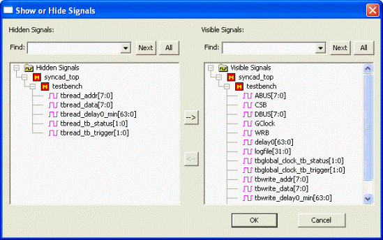
- New dialog for hierarchically showing and hiding signals via mouse selection or using
regular expression pattern matches.
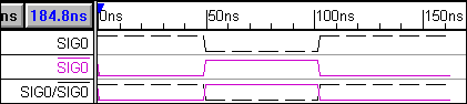
- Differential signals can now display a list of their member signals in the Label window
in lieu of their own name. Differential signals are a special type of Group Bus. They display a superimposed
image of two signal waveforms on top of each other. Each of the original signals. formatting is displayed
by the differential signal. The original signals can be hidden so that the final diagram will only display
the resulting differential signal.
- Now there is a fast method for shifting all the edges on a set of selected signals using
Edit Waveform Edges menu.
- In WaveFormer Pro, the menu option View > Show Default Simulated Signals Color
toggles whether simulated signals are drawn in the usual simulated waveform color (purple) or the ordinary
waveform color (black by default).
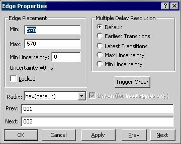
- Improved edge properties dialog displays next and previous state values as well as edge
times.
Analog Features
- A tutorial that covers creating and displaying analog signals.
- Ability to export real-radix signals as true piecewise-linear voltages or to approximate
stepped voltage sources by clicking Use Straight Edges in the Analog Properties dialog (both methods
use SPICE PWL statements).
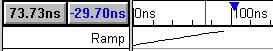
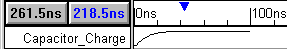
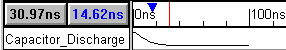
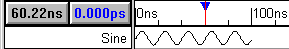
- New State label equation for quickly generating an analog waveform that represents:
- a Ramp starting at a given voltage and ending in a given voltage over a given duration
- a Capacitor charging over a given time-constant
- a Capacitor discharging over a given time-constant
- a Sine wave waveform
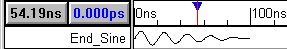
- a Sine wave that starts from zero and grows in amplitude
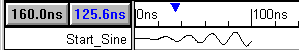
- a Sine wave that dwindles to zero
Text Objects
- Text objects can now be attached to a position relative to a corner of the diagram window.
This is handy for making titles or logo image files stick to a particular position on the screen.
- Text and Edge Alignment settings can now be set for either the current diagram or as
defaults for all new timing diagrams.
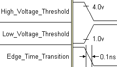
- Text objects can be set to display the rise/fall times and voltage thresholds of the
signals to which they are attached and the edge time transition points. The signal.s analog properties
determine the placement of the marking lines and the values of the properties.
Miscellaneous Features
- Drawing Preferences (Style Sheet) can now be used to edit either the current
diagram or the default settings for new diagrams.
- Chapter 8.7: Drawing Preferences dialog now has the New Diagram Default Style
and the Active Diagram Style radio buttons.
- Improved documentation for Section 15.7: Pattern Matching.
DataSheet Pro provides documentation professionals with an integrated environment for working with multiple
timing diagram documents. All the new WaveFormer Pro and Timing Diagrammer Pro features are also in
DataSheet Pro (with the exception of built-in software options).
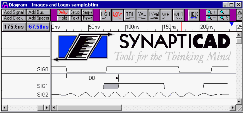
- Images and logo files can be displayed within a timing digram by linking the image file
to a text object. Once DataSheet Pro saves an image to a diagram it can be viewed in any of our timing
diagram products including the free WaveViewer software.
- Text objects can now be attached to a position relative to a corner of the diagram window.
This is handy for making titles or logo images stick to a particular position on the screen.
- Quickly scroll and zoom to a particular location on the timing diagram using the new
View function.
- Waveform Comparison display has been sped up and the differences are now displayed more
visibly with a red background, rather than a red waveform.
- Manage viewing a large number of signals using filter patterns in the new Show and Hide
Signals dialog accessed through the View > Show and Hide Signals menu.
- Create SVG images of diagrams. This format is a web-ready, XML-based, 2-dimensional
graphics format that is supported by many graphics tools across many platforms. Chapter 9.2: Embedding
Images into Documents.
BugHunter Pro is an interactive graphical debugger for Verilog, VHDL and C++. VeriLogger Pro bundles
BugHunter Pro with VlogCmd, our interpreted Verilog simulator.
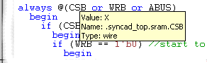
- Enhanced debugging tool tips show hierarchical name and type as well as current value.
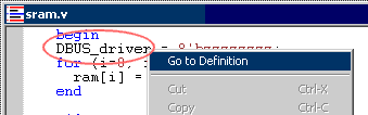
- Go to Definition allows quicker traversal of VHDL and Verilog code. Jumps from HDL instance
names and procedure calls to the declaration for the module/entity/architecture, task/function/procedure,
or signal/variable/net.
- Support has been added for SynaptiCAD's new Verilogger Extreme compiled-code simulator.
- Updated support for both the ModelSim and ActiveHDL simulators.

TestBencher Pro generates test benches from graphical timing diagrams.
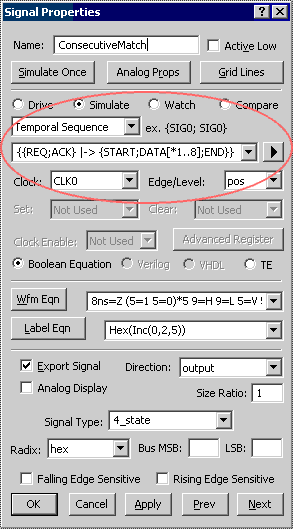
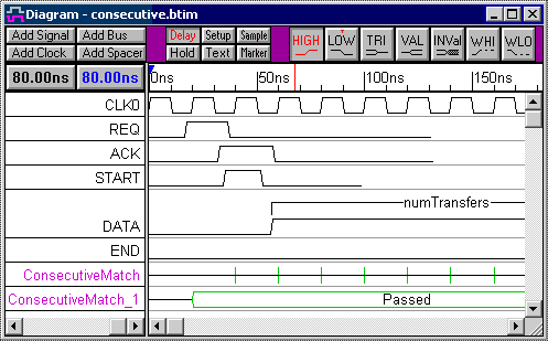
- Optional Transaction Tracker tool for analyzying waveforms with Accelera PSL 1.1 assertions.
PSL assertions are created the same way that Boolean equations are, using the Signal Properties dialog.
There's never been a better way to harness the power of PSL to detect errors in your designs.
- Simulation-created sticky notes allow Verilog and VHDL code to generate graphical
objects that are displayed on the simulation result waveforms.
- Simulation-created timing parameters allow Verilog and VHDL code to generate graphical
delays, setups, and holds on the simulation results waveforms.
- Ability to save waveforms to compressed BTIM format. (200x smaller than equivalent VCD
files and load 500x faster)
- PLI library that allows VHDL and Verilog simulators to directly dump to BTIM, speeding
up simulation times over 3x compared to dumping to VCD.
- New filter files allow user to selectively load sets of signals from a waveform
data file and set the signal properties and the order in which the signals are displayed.
- Improved rendering of analog waveforms.
- A quick-start tutorial covering the new features.
New Features pages for previous versions:
List of Features in Version 10.0
List of Features in Version 9.0
|