|
|||||||||||||||||||||||||||||||||||||||||||||||||||||||||||||||||||||||||||||||||||||||||||||||||
|
|

Free yourself from the time-consuming process of writing Verilog and VHDL test benches by hand. Generate them graphically from timing diagrams using SynaptiCAD's TestBencher Pro, WaveFormer Pro, DataSheet Pro, VeriLogger, and BugHunter Pro products. With 3 levels of test bench generation you can choose the product that meets the type and complexity of your testing needs. For basic test benches, WaveFormer can import waveform data from just about anywhere and generate stimulus vector test benches in a matter of minutes. BugHunter and VeriLogger also support basic stimulus generation and also include a fast, interactive unit-level testing environment. For more testbench flexibility, the Reactive Test Bench generation Option can be added to generate single timing diagram based test benches that react to the model under test. And for the most complex testing needs, TestBencher Pro generates test benches that are complete bus-functional models that monitor and react during runtime simulations.
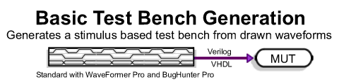
WaveFormer Pro, Data Sheet Pro, and BugHunter come with the basic stimulus test bench generation features. Drawn waveforms are used to generate stimulus models. The BugHunter features are tightly integrated into the simulation environment to allow quick interactive testing of design models.
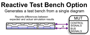
The Reactive Test Bench Generation Option is an option that can be added to WaveFormer Pro, DataSheet Pro, and the BugHunter Pro products. This option allows users to create self-testing test benches from a single timing diagram which generate error reports and react to the model under test during simulation. It also enables generation of "clocked test benches" that update stimulus based on one or more clock signals.
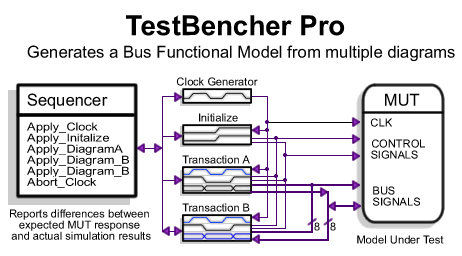
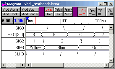
The highest level of testbench generation is provided by TestBencher Pro, which allows a user to design bus functional models using multiple timing diagrams to define transactors and a sequencer process to apply the diagram transactions. TestBencher can be added to BugHunter or purchased as a standalone product. Code Generation ExamplesIn the following examples we will show you how some of our customers have used each of these products. We will also show some code samples so you can get an idea of exactly what type of code is generated for each product. WaveFormer Pro and DataSheet Pro Example Stimulus CodeWaveFormer Pro and DataSheet Pro generate VHDL and Verilog stimulus models from waveforms that are displayed in the timing diagram window. Both of these products are timing diagram editors with features that are described in WaveFormer Pro and DataSheet Pro pages. For generating quick and small test benches, the drawing environment can be used to develop the stimulus vectors. This is much faster and accurate than attempting to hand-code a small test bench, because the temporal relationships between edges are easier to see in a graphical timing diagram then in raw VHDL or Verilog code. For large test benches, the waveform data can be imported from an outside source like a logic analyzer, simulator, or spreadsheet. For example, one customers designed an ASIC for use in an existing communications system. He used a logic analyzer to capture stimulus vectors from the communications system, then used WaveFormer to translate the data into a VHDL test bench which he used to test the ASIC design. Once a timing diagram is finished, code generation is simply a file save operation using the Export > Export Timing Diagram menu option. WaveFormer generates either a Verilog model or a VHDL entity/architecture model for the stimulus test bench. This test bench model can then be instantiated in a user's project and compiled and simulated with the rest of the design. Below is an example of a timing diagram and some of the VHDL code that was generated from the timing diagram. In the generated code, notice that the clock is a parameterized process. During simulation, a user can easily modify the operation of the test bench by changing the values of the clock variables. WaveFormer also supports complex data types and user-defined types. Notice that SIG1 has a VHDL type of integer. In WaveFormer, the VHDL and Verilog types of signals can be changed using the Signals Properties dialog. VHDL user-defined types can also be entered through the same interface.
-- Generated by WaveFormer Pro Version
library ieee, std;
use ieee.std_logic_1164.all;

entity stimulus is
  port (
    SIG0 : out std_logic := 'Z';
    SIG1 : out std_logic_vector(3 downto 0) := "ZZZZ";
    SIG2 : out integer;
    SIG3 : out MyColor;
    CLK0 : out std_logic := 'Z');
	-- more entity code
end stimulus;

architecture STIMULATOR of stimulus is

  -- some signal and parameter declarations

begin

  -- clock and status setup code

  -- Clock Process
  CLK0_process : process
    variable CLK0_low : real;
    variable CLK0_high : real;
  begin
    tb_mainloop : loop
      wait until (tb_status = TB_ONCE)
                 or (tb_status = TB_LOOPING);
      CLK0_high := CLK0_Period * CLK0_Duty / 100.0;
      CLK0_low := CLK0_Period - CLK0_high;
	  -- more clock code
    end loop;
  end process;

  -- Sequence: Unclocked
  Unclocked : process
  begin
    SIG0_driver <= '0';
    SIG1_driver <= x"3";
    SIG2_driver <= 1;
    SIG3_driver <= Yellow;
    wait for 45.0 ns;
    SIG1_driver <= x"F";
    wait for 5.0 ns;
	-- more signal statements
    wait;
  end process;
end STIMULATOR;
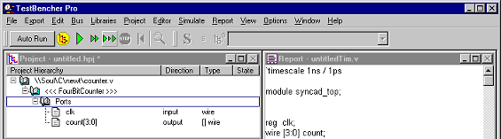
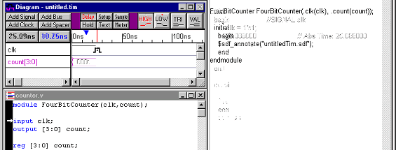
BugHunter Pro and VeriLogger Extreme - Fast Unit-Level TestingBugHunter Pro is the graphical debugging interface for VeriLogger Extreme and other commercial VHDL and Verilog simulators. It is unique in that we have integrated our test bench generation features very closely with the simulator engine. Model testing is so fast in BugHunter Pro that you can perform true bottom-up testing of every model in your design, a critical step often skipped in the verification process because it has traditionally been very time consuming. Once finish writing an HDL model for your design, BugHunter Pro will extract the signals or the ports in the top-level module and automatically add them to the Diagram window. The output ports are displayed as purple (simulated) signals and input ports are displayed as black signals. Input signals waveforms can be graphically drawn, generated by equations, or copied from existing signals. When a simulation is requested, BugHunter automatically wraps a test bench around the top-level module and creates signals in this test bench to drive and watch the top-level module. BugHunter can also be put into an interactive simulation mode, so that each time an input signal is changed, a new test bench is generated and a simulation is performed. This makes it easy to quickly test small parts of a design before the design is complete. It also allows you to quickly test ideas without being forced to generate a comprehensive test bench. In the below example, we have hand coded a 4-bit Adder model and we wish to quickly test the model. First we put the "add4.v" file into the Project window and press the yellow build button. BugHunter then scans the model and checks for syntax errors and inserts the top-level ports into the timing diagram window. At this point, the user can begin to draw waveforms on the black input signals. Since BugHunter is in the "Sim Diagram & Project" mode, when the user presses the green run button, BugHunter will generate a test bench from the drawn input waveforms and perform the simulation. Outputs of the simulation will be displayed in the same diagram as the input stimulus. In the interactive simulation mode, re-simuluations occur automatically whenever the user changes the input stimulus, making it easy to test a small change in the timing of an input signal. If the user wants to archive off a testbench and associated simulation results, all he has to do is save the timing diagram file and reload it at a later date. The completed test bench and wrapper code can be viewed in the report window. |
|
|
|
BugHunter's automatic test bench generation features are perfectly suited for testing small models. But as a design grows in complexity, more complex test benches are also needed to ensure the functionality of the overall design. TestBencher Pro was designed to meet this need. TestBencher enables the rapid creation of bus-functional models for transaction-level testing of your complete system.
TestBencher Pro - Advanced Bus-Functional Models
TestBencher Pro generates VHDL and Verilog test benches directly from timing diagrams using a bus functional approach to test bench designs. It is used to model complex test benches like a microprocessor or bus interface. With TestBencher, users can generate a test bench in a few hours that would normally take several weeks to test and code by hand.
Bus-functional models execute faster than complete functional models and can be created from data contained in data sheets. A bus-functional model is also easier to maintain and debug than raw test vector data. The code that is generated for each project is native VHDL or Verilog. This allows the generated code to be compiled with the model under test and simulated using all major VHDL and Verilog simulators. Debugging the resulting system is easy since the test bench is structured into transactions and all of the generated code uses the same language as the code being tested.
Graphical Representation of Transactions
TestBencher Pro uses timing diagrams to represent the timing transactions of the test bench. By using
timing diagrams, the engineer can work with a higher level abstraction, free from the tedious details
of the underlying code. This graphical representation facilitates the collaboration of many engineers
on a single test bench by removing the need to interpret source code. Any engineer familiar with the
design specifications is able to look at a given timing diagram and have an immediate understanding
of what the transaction is doing. This level of abstraction also provides a great aid in terms of maintainability.
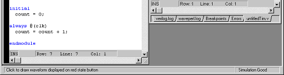
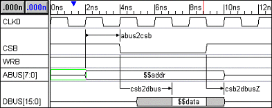
In the example below, we have hand-coded a very simple timing transactor (a model that generates or responds to transactions) to show how difficult it is to understand even a small segment of code. Also shown is the timing diagram that can be used to generate this transactor. A glance at the timing diagram communicates the temporal relationships between the edges of the signals. The code segment has to be studied and possibly drawn out by hand to figure out the temporal relationships of the signals.
module testbench;
...
task write(addr,data,csb2dbus);
  input [7:0] addr;
  input [15:0] data;
  input [1:0] csb2dbus;
begin
    ABUS = addr;
  @(posedge CLK0)  //required abus2csb setup
    CSB = 1'b0;
  repeat (csb2dbus) @CLK0;
    DBUS = data;
  @(posedge CLK0)
    CSB = 1'b1;
    DBUS = 'hz;
    ABUS = 'hz;
end
endtask
...
endmodule
Code complexity greatly increases when response checking code and parallel execution blocks are added to a transactor. In the previous example, only one process block is needed to represent the transaction. However, if you wanted the transaction to sample the first edge transition of CSB then do a conditional delay of the csb2dus, the transactor has to be coded like a finite state-machine. This type of coding is very difficult to read, however the timing diagram is still easy to interpret.
Automatic Tracking of Signal and Port Code
One of the most tedious aspects of working with HDL languages is maintaining the signal and port information
between the test bench and the model under test. Signal information is repeated at several levels of
the test bench, so a change in the signal information requires a tedious rewriting of the test bench
code. Test bench code is more difficult to maintain than a regular design model because the code is
not broken apart into simple units. Each timing transactor usually drives and monitors most of the
input/output port signals of the model under test. TestBencher solves this problem by maintaining the
signal and port information for all the timing transactions and the model under test. With TestBencher
Pro, a signal change is made in one place and then automatically propagated to all the places where that
code needs to be represented. Without this capability, port-connection errors can easily arise leading
to subtle, difficult to debug errors, similar to the problems that arise when pins are misconnected
on a circuit board.
Conceptual Modeling Constructs
TestBencher is easy to use because we have taken great care to keep the number of constructs down to
a minimum. There are 5 basic constructs that are used to create a transaction. It is easier to learn
the functionality of these 5 graphical constructs than it is to figure out how to out how to code manual
equivalents into a transactor model.
- Drawn Waveforms - describes stimulus and expected response
- State Variables - parameterize state values
- Delays - parameterize time delays between edge transitions
- Samples - verify and react to output from model under test
- Markers - models looping contructs or to insert native HDL subroutine calls
These graphical constructs look and act the way that you expect a timing diagram to work, making it very easy to create a timing diagram that generates code that you expect to be generated. Normally an engineer must manually perform this conversion from data sheet timing diagrams to HDL code.
Easier to Maintain Test Benches
TestBencher Pro's test benches are easier to maintain than hand coded test benches for several reasons:
- Graphical representation of transactions facilitates the ability of a non-author to understand the basic operation of the test bench.
- A project window contains all of the related test bench and model under test files so that an engineer can quickly move through the test bench and MUT code.
- Limited number of files generated (1+N transactions). One file is generated for the top-level test bench, and one file is generated for each timing transaction.
- Fast generation of code - each time a transaction is saved, the code for that transaction is re-generated so that you can immediately assess the effects of changes in the timing diagram.
- Generation of optimized test bench code for fast test bench execution.
- All generated code is well documented - both in comments and in naming constructs, making the generated code easier to understand.
- The use of generated code guarantees consistent code architecture. This provides readability from one transactor to the next, and from one project to the next.
- GUI environment isolates key parameters of the test bench for easy modification.
- Generated code automates the checking of simulation results, freeing the engineer from needing to manually view waveform results to ensure proper operation of his design.
TestBencher Pro abstracts coding details away from the user, and by doing so reduces the amount of time needed for test bench generation. By automating the most tedious aspects of test bench development, high paid engineers can focus on the design and operation of the test bench rather than the painstaking aspects of code development.
Reactive Test Bench Option
The Reactive Test Bench Option is a sub-set of the TestBencher Pro product. It enables the creation of self-testing testbenches using a single timing diagram, rather than the multi-diagram bus-functional models created by TestBencher Pro. The Reactive test benches can respond to the model under test during simulation and also generate reports that describe the performance of the simulation. The Reactive Test Bench Generation Option can be added to WaveFormer Pro, WaveFormer Lite, DataSheet Pro, and BugHunter Pro.
With Reactive Test Bench Option, the user draws both the stimulus waveforms (black) and the expected output of the model under test (blue waveforms). Samples are added to the blue expected waveforms to generate specific tests at those points in the diagram
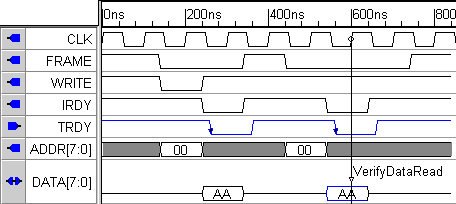
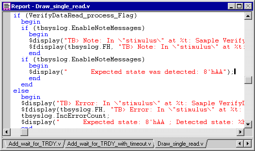
Below is a picture of the generated code for the sample that is used to check the output of the read cycle.
Summary
SynaptiCAD offers 3-levels of test bench generation to fit your design and verification needs. WaveFormer for producing stimulus based test benches. VeriLogger for fast unit-level testing. TestBencher for producing complex bus-functional models to represent complex, reactive interfaces. Whether you take advantage of our unit-level, our system level testing tools, or both, SynaptiCAD's test bench products will save you time.