TestBencher Features
TestBencher is a system level test bench generator that creates bus functional models from language
independent timing diagrams. All the generated code is native VHDL, Verilog, or SystemC so
it can be simulated using any major simulator.
System Level Features
TestBencher automates the most tedious aspects of test bench development, allowing you to focus on the
design and operation of the test bench. This is accomplished by representing each bus transaction graphically
and then generating the code for the transaction.
-
VHDL, Verilog, and SystemC language generation.
-
Bus-functional model generation from graphical timing diagrams.
-
Hierarchical Models supported.
-
Multiple Component Instantiation supports multi-port designs.
-
Built-in Timing Diagram Editor for creating bus transactions.
-
Data Sources and Targets automatically generate all of the File I/O code and class definitions.
-
Sequence Recognition verifies timing sequences.
-
Pipelining Transactions can be used to implement a pipelined bus master.
-
Cycle and Event based test benches.
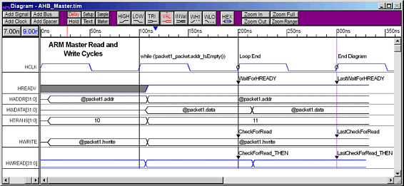
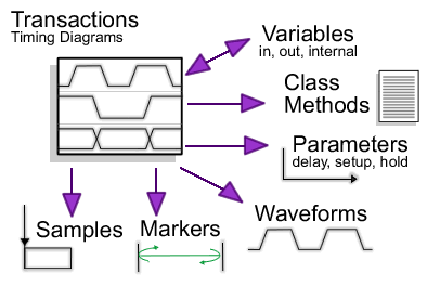
Transaction Representation Features
TestBencher ships with a built-in timing diagram editor that is used to define the transactions for
the generated test bench. Using the timing diagram editor you can quickly model common bus activities
such as driving control signals, sampling and verifying values from the model under test (reporting
unexpected values or transitions), waiting for handshaking signals before completing transaction, and
aborting a transaction under a reset condition.
-
MUT Signal Extraction - extracts the port signals from the MUT and places into diagram with signal
properties correctly set up (i.e. direction, type, and size are set automatically).
-
Clocked to/from Un-clocked Operations - Conversion between clocked and un-clocked diagrams can
be done in just one step. Also, diagrams can contain any mix of un-clocked and clocked items.
-
Delays - make one event relative to another (delay features section).
-
Samples - react to output from the MUT or other diagram transactions (sample
features section).
-
Markers - used to indicate loops, insert HDL code, and end the diagram.
-
Holds - performs a single hold check.
-
Setups - performs a single setup check.
-
File Input - reads data from a spreadsheet formatted file to drive signals (input to the MUT)
-
File Output - outputs sampled data to a spreadsheet formatted file.
-
Class Generation - used to create user-defined classes (data structures) that can contain queues,
arrays, and associative arrays (data sources and targets).
-
Sequence Recognition - detects or verifies a sequence of events expected from the MUT output.
-
Macros - used to define commonly used constants and reference in diagram by using name.
-
State Variables - used to specify that a particular state will be passed into the transaction's
apply function during simulation.
-
Conditional Drives - drive a state to different values based on a condition represented by an
HDL Boolean expression.
-
Compare Signals - used to specify what a MUT output signal should look like during an entire
transaction.
-
Simulated Signals - uses a language independent equation to represent the behavior of the signal.
-
Registers - used to model many difference types of registers of which you can specify signals
for Clock, Clear, Set, and Clock Enable. The active level of Set, Clear, and Clock Enable is selectable
by the user and Clock-to-Out delays can be specified. Also, setup and hold requirements can be specified
for the register, which will cause errors to be reported if they are violated.
-
Parameter Functions - the minimum or maximum value of a parameter (such as a Sample or Delay)
can be defined as a function to be calculated at simulation-time.
-
Verbose Logging - the diagram has verbose options for Samples, Delays, Sequence Recognition,
and File I/O. When turned on, the actions of these constructs are reported verbosely to the simulation
log file.
VHDL and Verilog Support
TestBencher Pro generates VHDL and Verilog test benches with the capability of hooking up to C++ libraries.
The library support adds powerful constructs to like random data generation and advanced data structures
that are not available in native VHDL or Verilog.
-
C++ based library integration using the open TestBuilder libraries.
-
Constrained Random Data generation with TestBuilder support.
-
Temporal Equations with TestBuilder support.
-
Automatic generation of TestBuilder-style test benches.
SystemC Support
TestBencher Pro provides designers with a graphical environment for generating SystemC test benches
from language-independent timing diagrams.
Delay Features
Delays are graphical timing diagram elements that are used to make one event relative to another. In
TestBencher, delays can be used conditionally move edges based on parameterized time values, or conditionally
trigger control signals.
-
Delay Time can be specified in terms of time or clock edges.
-
Parameterize Times by passing in the value through the apply function for the diagram, or by
reading the value from a file.
-
Conditionally Execute delays by specifying a condition that determines when to execute the delay.
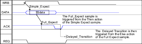
Sample Features
Sample parameters generate self-testing code that is used to store, verify, and react to data produced
by the system being tested. Samples will sample the signal, compare the sampled state to the state drawn
beneath the Sample, and report a warning message if they differ. In addition to many reporting options,
Samples can be used to control the execution path of the diagram and output data to files and memory.
Samples can be used to do all of the following:

-
Automatically Verify outputs from the MUT.
-
Wait until an edge or particular state value occurs.
-
Check Stability of a signal during a specified region.
-
Sequence Verification checks to see that a sequence of events occurs.
-
Log Simulation Run-Time Messages with option of four different severity levels - Note, Warning,
Error, and Failure. The Failure severity level will cause the simulation to end immediately.
-
Restart the transaction.
-
End the transaction.
-
Trigger Delays and other Samples to set up a logical path of diagram execution and error checking.
-
Write sampled data to file.
-
Write sampled data to memory which can be used to drive states or used to compare against other
states later in the same simulation or in another simulation run.
-
Conditionally reads or stores data based on the condition.
-
Block the triggering process, and hence the entire diagram if everything is using the same clock.
The blocking option can be turned on and off for each Sample individually.
Marker Features
Timing Diagram Markers can be added to specify actions to be taken by the transaction during execution.
These actions can include signifying the end of a transaction, waiting for a condition, looping, or
executing algorithmic HDL code.
-
Create Loops for burst mode transactions
-
Conditionally Stop Entire Transaction until a particular condition is met.
-
Call an HDL function to perform a function that is difficult to represent graphically.
-
End Transaction markers cause code generation to stop a particular time or clock cycle.
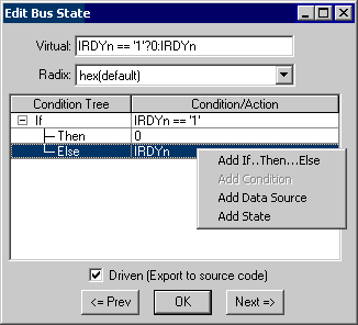
Signal State Features
TestBencher Pro can define a signal's value graphically by drawing the waveform or by defining it using
several types of expressions.
-
Signal state values can be specified as full expressions including Boolean equations that reference
state variables and user-defined data structures.
-
Signal states can contain conditional expressions that determine at run-time what value to drive
based on the value of other variables in the simulation.
-
Boolean equations are language independent, further simplifying conversion of a test bench from
one target language to another.
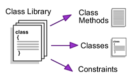
Classes and Class Library Features
In addition to the graphical elements of a project, TestBencher also supports generation of user-defined
classes and variables. Classes, which are stored in class libraries, contain data fields and methods.
These elements let you pass data around and compose algorithmic functions that are not easy to define
graphically.
-
Generate File I/O code automatically
-
Create Packet Data Structures for passing data into and out of transactions.
-
Create Memories, FIFOs, and Stacks for driving tests.
-
Create Regression Test Suites
-
Variables can be scoped at the diagram level as well as the top level.
Top-Level Test Bench Control
TestBencher Pro provides a Project Wizard and Project level settings that help you create and maintain
the test bench.
-
Project Wizard simplifies creating new test benches.
-
Model Under Test is automatically instantiated in the top-level test bench.
-
Multiple instantiation of TestBencher projects, allowing you to build system-level test benches
using a bottom up approach.
-
Switch between cycle-based and time-based versions of a test bench with the click of a button.
-
Graphical port editor for modifying a project component's ports.
-
Template Diagram feature allows the user to specify a template of a diagram that is used when
creating new diagrams in a given project. The most common usage of template diagrams is to extract the
port information from your model under test into the template diagram so that all future diagrams you
create in that project will already contain the model's port signals.
-
Project tree interface organizes the different components of the test bench into separate folders
on the tree.
Multiple Test Bench Components
TestBencher Pro uses a project file to control the generation of the test bench bus-functional model.
Multiple test bench components can be made by including a project inside of another project, and then
instantiating the sub-project. This lets you develop and verify complex test benches in an incremental
manor.
Sequence Recognition
TestBencher Pro has the ability to create a state machine within a timing transaction. This state machine
can be used to ensure that a specific sequence of events occurs on one or more signals prior to the
transaction proceeding.
External Program Integration
TestBencher Pro can launch simulators and compilers automatically, and hand off the generated code so
it is very easy to move from test bench development to simulation. TestBencher can also import waveforms
from many different formats making diagram creation easier and faster. TestBencher can also import the
final simulation results so that they can be viewed graphically.
-
Automatically launch ModelSim and send commands to the graphical interface to display the test
bench control and status signals.
-
Graphical integration and control of VCS, VERA, and Verilog-XL using TestBencher's simulation
button bar.
-
Automatic launching of Microsoft's C++ and GNU compilers for SystemC and TestBuilder code.
-
Remote execution of VCS and Vera running on different computers and even under different operating
systems. This means you can use a Windows PC as your desktop machine and transparently run your simulations
as batch jobs on a Solaris box.
-
Simulator settings are saved for each language individually, so that you can (for instance) simulate
OpenVera projects with VCS and VHDL projects with ModelSim, without having to change the settings each
time you switch between languages.
-
Import/Export formats TDML, VCD, SpeedWave VHDL, Workview WFM, Agilent Logic Analyzer, Agilent
Fast Binary Out, Agilent Wave Logic Analyzer, Agilent Infinium Digitizing oscilloscope, Podalyzer Data,
Peak VHDL AWF, DesignWorks, Timing Designer, Protel Advanced PLD, AWF, VHDL Waves Vectors (Actel), Altera
table Format, Spice CSDF format, and more.
-
Graphically Display Simulation Results by importing simulation vectors.
|