|
|||||||||||||||||||||||||||||||||||||||||||||||||||||||||||||||||||||||||||||||||||||||||||||||||||||
|
|
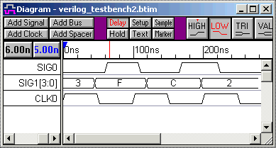
WaveFormer Pro Exports Verilog Stimulus ModelsWaveFormer can generate Verilog stimulus models from waveforms that are displayed in the timing diagram window. For generating quick and small test benches the drawing environment can be used to develop the stimulus vectors. This is much faster and accurate then attempting to hand code a small test bench, because the temporal relationships between edges are easier to see in the graphical timing diagram than in the raw Verilog code. For large test benches, the waveform data can be imported from an outside source like a logic analyzer, simulator, or spreadsheet. For example, one of our customers designed an ASIC for use in an existing communications system. He used a logic analyzer to capture stimulus vectors from the communications system, and then used WaveFormer to translate the data into an HDL test bench, which he used to test the ASIC design. Once a timing diagram is finished, code generation is simply a file save operation using the Export > Export Timing Diagram menu option. Below is an example of a timing diagram and some of the Verilog code that was generated from the timing diagram.
WaveFormer generates a Verilog model for the stimulus test bench. This test bench model can then be instantiated in a user's project and compiled and simulated with the rest of the design.
module stimulus(SIG0, SIG1, CLK0);
  output SIG0;
  output [3:0] SIG1;
  output CLK0;

  //more declarations

  // The following initial block will start up the stimulator.
  initial
    begin
    AssignParms;
    tb_status <= `TB_ONCE;
    Unclocked;
    $display("Note: At %t: End of stimulus reached.
              Use End Diagram Marker to extend or
              shorten stimulus.", $time);
    tb_status <= `TB_DONE;
    end

  // Clock Instantiation
  tb_clock_minmax #(1) tb_CLK0(tb_status[1:0],
            CLK0,
            CLK0_Offset_bits,
            CLK0_Period_bits,
            CLK0_Duty_bits,
            CLK0_MinLH_bits,
            CLK0_MaxLH_bits,
            CLK0_MinHL_bits,
            CLK0_MaxHL_bits,
            CLK0_JRise_bits,
            CLK0_JFall_bits);

  // Sequence: Unclocked
  task Unclocked;
    begin
    SIG0_driver <= 1'b0;
    SIG1_driver <= 4'h3;
    #45.0;
    SIG1_driver <= 4'hF;
    #16.0;
    SIG0_driver <= 1'b1;
    #48.0;
    SIG0_driver <= 1'b0;
    #10.0;
    SIG1_driver <= 4'hC;
    #48.0;
    SIG0_driver <= 1'b1;
    #30.0;
    SIG1_driver <= 4'h2;
    #25.0;
    SIG0_driver <= 1'b0;
    #69.0;
    end
  endtask
endmodule


module tb_clock_minmax(//clock parameters);

  //clock loop code

endmodule
WaveFormer ships with two scripts for exporting Verilog stimulus test benches. Both the Verilog and Verilog w/ Top Level Test Bench export scripts export a complete module for the stimulus model. The Verilog w/ Top Level Test Bench export script is designed to work with external simulators like Actel design software. The third party software passes WaveFormer a project file containing the users model under test code. WaveFormer parses this code and inserts signals into an empty timing diagram. When the top-level script is called an extra module test bench is created that instantiates the stimulus model and the users model under test. SynaptiCAD's TestBencher Pro, VeriLogger Pro, and WaveFormer Pro each generate a different type of Verilog test bench. WaveFormer generates the simplest stimulus based test bench. The VHDL and Verilog Test Bench Synthesis page describes the different types of test benches that are generated. |
|
|