|
|||||||||||||||||||||||||||||||||||||||||||||||||||||||||||||||||||||||||||||||||||||||||||||||||||||
|
|
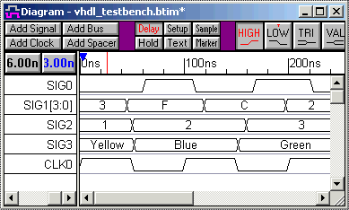
WaveFormer Pro Exports VHDL Stimulus ModelsWaveFormer can generate VHDL stimulus models from waveforms that are displayed in the timing diagram window. For generating quick and small test benches the drawing environment can be used to develop the stimulus vectors. This is much faster and accurate then attempting to hand code a small test bench, because the temporal relationships between edges are easier to see in the graphical timing diagram than in the raw VHDL code. For large test benches, the waveform data can be imported from an outside source like a logic analyzer, simulator, or spreadsheet. For example, one of our customers designed an ASIC for use in an existing communications system. He used a logic analyzer to capture stimulus vectors from the communications system, and then used WaveFormer to translate the data into a VHDL test bench, which he used to test the ASIC design. Once a timing diagram is finished, code generation is simply a file save operation using the Export > Export Timing Diagram menu option. Below is an example of a timing diagram and some of the VHDL code that was generated from the timing diagram.
WaveFormer generates a VHDL entity - architecture model for the stimulus test bench. This test bench model can then be instantiated in a user's project and compiled and simulated with the rest of the design.
entity stimulus is
  port (
    SIG0 : out std_logic := 'Z';
    SIG1 : out std_logic_vector(3 downto 0) := "ZZZZ";
    SIG2 : out integer;
    SIG3 : out MyColor;
    CLK0 : out std_logic := 'Z');
    -- more entity code
end stimulus;

architecture STIMULATOR of stimulus is
  -- architecture code
end STIMULATOR;
WaveFormer supports complex data types like integers and user-defined types. Each signal has a set of export properties like type, size, direction, and radix that determine how the signal is exported. These properties are set in the Signal Properties dialog by double clicking on the signal name. Signal transitions are implemented using wait statements like: -- Sequence: Unclocked Unclocked : process begin SIG0_driver <= '0'; SIG1_driver <= x"3"; SIG2_driver <= 1; SIG3_driver <= Yellow; wait for 45.0 ns; SIG1_driver <= x"F"; wait for 5.0 ns; -- more process code end process; The clock is generated as a parameterized process. SynaptiCAD's clocks can be defined using equations and these equations are also exported. The status signal turns the clock off during simulation when the stimulus is completed.
-- Clock Process
CLK0_process : process
 variable CLK0_low : real;
 variable CLK0_high : real;
 begin
  tb_mainloop : loop
    wait until (tb_status = TB_ONCE)
            or (tb_status = TB_LOOPING);
    CLK0_high := CLK0_Period * CLK0_Duty / 100.0;
    CLK0_low := CLK0_Period - CLK0_high;
    --more clock code
  end loop;
end process;
WaveFormer ships with two scripts for exporting VHDL stimulus test benches. Both the VHDL and VHDL w/ Top Level Test Bench export scripts export a complete entity-architecture test bench for the stimulus model. The VHDL w/ Top Level Test Bench export script is designed to work with external simulators like Actel design software. The third party software passes WaveFormer a project file containing the users model under test code. WaveFormer parses this code and inserts signals into an empty timing diagram. When the top-level script is called an extra entity-architecture test bench is created that instantiates the stimulus model and the users model under test. SynaptiCAD's TestBencher Pro, VeriLogger Pro, and WaveFormer Pro each generate a different type of VHDL test bench. WaveFormer generates the simplest stimulus based test bench. The VHDL and Verilog Test Bench Synthesis page describes the different types of test benches that are generated. |
|
|