|
|||||||||||||||||||||||||||||||||||||||||||||||||||||||||||||||||||||||||||||||||||||||||||||||||||||||||
|
|
Coding Techniques for Bus Functional Models In Verilog, VHDL, and C++By Ben Rhodes and Dan Notestein, SynaptiCAD Bus functional models are simplified simulation models that accurately reflect the I/O level behavior of a device without modeling its internal computational abilities. For example, a bus functional model of a microprocessor would be able to generate PCI read and write transactions to a PCI device model to initialize and test the PCI device's functionality, but the microprocessor BFM would not be capable of reading CPU instructions from a memory and properly executing the instructions (this would require a complete behavioral level model of the processor). Bus functional models are commonly used in test benches to stimulate design models and verify their functionality. For the purposes of this paper, the designs models being tested are either RTL or gate-level models of the system. Using transactors to model transaction signaling protocolsBus functional models typically serve as an abstraction layer between the transaction level of system functionality which describes what data is being exchanged between two devices and the signaling level which dictates how this data is exchanged during the transaction. At the transactional level, a transaction can be viewed as a simple function call with parameters for the data being exchanged. At the signaling level, this is converted into signal transitions on appropriate clock cycles along with handshaking logic to ensure the data exchange is properly synchronized. The part of the BFM that performs the signaling when a transaction function is called is known a transactor. Transactors are the only parts of a BFM that interact directly with the signals of a design model; the remaining code in a BFM manipulates only transaction level data. The figure below demonstrates how transactors serve as an interface between the transaction level code in the testbench and the signals of the design model being tested.
Figure 1: Transactors are driven by the Transaction manager and stimulate the MUT For best simulation performance, transactors should generally be modeled in the language of the design under test since there is typically a performance penalty for simulation activity that occurs across simulation language barriers, whereas it is often convenient to model the transaction level part of the BFM in a language that directly supports data structures and dynamic memory allocation. There is usually little if any penalty in writing the transaction level code in a higher level language since data is being worked with in larger chunks that doesn't need to interact as much with the simulation kernel. Master and slave transactorsTransactors can be divided into two broad categories: master transactors that initiate a transaction and slave transactors that respond to a master transactor. Master transactors are generally modeled as procedures that are called whenever a transaction should be started, whereas slave transactors tend to be modeled as a group of related parallel processes that run for the entire simulation run, responding whenever they recognize a transaction is addressed to them. Although it is convenient from the point of view of the code that initiates master transactions to model master transactors as a procedure, the underlying implementation of a master transaction may also require the use of multiple parallel processes, which neither VHDL nor Verilog allow in functions. This problem can be overcome by modeling the master transactor as a state machine that responds to handshaking signals triggered by an "ApplyTransaction" procedure, making the master transactor look like a procedure call to the transaction-level code of the BFM. By default, this creates a transactor that does not block the calling process, but blocking transactions can be achieved by calling a version of the "ApplyTransaction" procedure call that waits for a completion signal from the transactor. It is frequently necessary to model a transaction as a set of cooperating processes, but this leads to two problems: (1) the processes must be synchronized so that they start and stop together and (2) it is easy to introduce races between when signals are sampled and driven. In Verilog, synchronization of the processes can be achieved using a fork-join to coordinate the processes. In VHDL, a pseudo fork-join can be used to simulate this effect. This technique uses a resolved handshaking signal that is monitored and driven by all the processes to be forked (see Writing Testbenches, Janick Bergeron, pp 135-137 for a detailed explanation of this technique). It is often desirable to be able to restart these processes during the middle of a transaction, effectively reseting the transaction. In Verilog, this can be done using disable statements, in VHDL it is more awkward, as it requires an abort status signal to be checked every time a wait statement is encountered in the transaction processes. By adding an additional state to the handshaking signal that handles the pseudo fork-join, we can reuse this signal as the abort status signal. This technique allows any of the processes in the pseudo fork-join to abort the transaction. Avoiding race conditions in transactor sampling codeRace conditions can arise in a transactor when you need to sample the value of a signal and drive other signals that could affect the value of the sampled signal. Generally this can be avoid by sampling the value prior to driving the other signals, but when multiple processes are involved the order in which these statements occur is no longer known. This can be avoided in simple cases by the use of non-blocking statements in Verilog (in VHDL, this is the default case as long as you're not using shared variables). However, if one of the processes enables the execution of another process through zero delta time handshaking signals, these extra delta times can still lead to race conditions. This kind of code often occurs when a condition in the first process enables the execution of the second process, for example, when a signal's stability needs to be checked after a particular clock edge. This kind of state sampling code can often be in-lined in the enabling process, but this is not possible in cases where the stability checking code includes wait statements that would block the execution of the enabling process. To solve this problem, the following method can be used:
Data structures and data packing for serializing of packet dataData structures are useful for modeling complex data at a high level of abstraction. This can be very helpful when passing data between modules and tasks since multiple pieces of data can be passed as a single logical unit. Classes are even more useful since tasks and functions can be associated with each data structure for encapsulating algorithms specific to the type of data structure, such as packing and randomization. Classes form the base of C++, but aren't available in VHDL and Verilog. However, you can create pseudo-classes in these HDL languages. In Verilog, you would create a module with regs, tasks and functions to represent a class. Two tasks need to be defined to convert the class to/from an array of bits in order to pass instance information across module and task boundaries (this is very similar to the concept of using $realtobits and $bitstoreal to pass real numbers across module boundaries). In VHDL, you can create a record to represent the data structure, usually placed in a package. For each class method, the first parameter should be an inout of the data structure record type to allow the method to operate on the internals of a particular data structure instance. A Verilog example is shown below.
module packet_type;
  reg [23:0] tb_packed_bits;
  reg [7:0] FIELD0;
  reg [7:0] FIELD1;

  function [23:0] tobits;
     input dummy;
  begin
     tb_packed_bits = { FIELD1, FIELD0 };
     tobits = tb_packed_bits;
  end
  endfunction

  task frombits;
     input [23:0] tb_packed_bits_in;
  begin
    tb_packed_bits = tb_packed_bits_in;
    { FIELD1, FIELD0 } = tb_packed_bits;
  end
  endtask
endmodule
Data packing is necessary when you need to translate data structures into information that can be understood by a bus protocol being used. It is very convenient to pass high level data structures around when working with a test bench, but usually at some point these data structures need to be transmitted across an actual bus in the hardware models. A nice way to do this is to create a class method that can be used to convert the data structure into either an array of bits or bytes (depending on the bus protocol). In Verilog, this could even be the same method that was written to pass the class across module and task boundaries, as described above. Below is an example of how to do this in VHDL:
type CLASS0 is record
  FIELD0 : bit_vector(7 downto 0);
  FIELD1 : bit_vector(7 downto 0);
end record;

function pack(this : CLASS0) return std_logic_vector is
  variable packed_data : std_logic_vector(15 downto 0);
begin
  packed_data(7 downto 0) := To_StdLogicVector(this.FIELD0);
  packed_data(15 downto 8) := To_StdLogicVector(this.FIELD1);
  return packed_data;
end function;

function unpack(packed_data : std_logic_vector(15 downto 0))
                     return CLASS0 is
variable dataStructure : CLASS0;
begin
  dataStructure.FIELD0 := To_bitvector(packed_data(7 downto 0));
  dataStructure.FIELD1 := To_bitvector(packed_data(15 downto 8));
  return dataStructure;
end function;
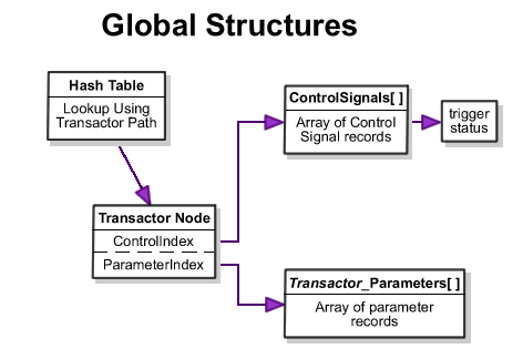
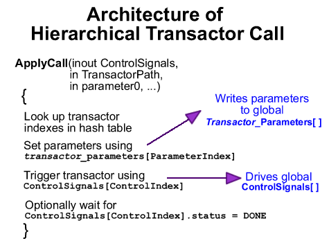
VHDL and Verilog do have some limitations when using these pseudo-class techniques. In Verilog, to pass a class instance into a module, it must first be converted into a bit array. Then, inside the task it must be converted back into a module instance. This means an additional module instance must be created that is available from the scope of the task that can be used to convert the bit array that was passed in to a data structure. Also, Verilog and VHDL pseudo-class solutions lack more advanced features available in C++ classes such as data hiding, inheritance, and polymorphism. Developing transaction generators and managers to stimulate a designOnce transactors have been created for a BFM, a transaction generator must be created that can generate the different types of transaction calls and the inputs for the transaction calls. The transactions are typically a mix of directed tests used to setup and test specific functionality combined with long runs of randomly generated transactions to catch any problem cases not caught by the directed tests. Constrained random testing is used when a system has too many potential input sequences to test all possible input sequences (a typical situation for virtually all system level designs) because they save time compared to manually writing the huge number of directed tests that would otherwise be required. The term constrained random is used to refer to randomly generated transactions that are constrained by the generator to meet some requirements on the randomly generated values. Typically the constraints are that the parameters to the transaction are logically consistent with one another and with respect to the transaction protocol and the implementation of the design under test. For example, the address values to a read transaction might be constrained so that most of them are within the address space of the device under test. By constraining the parameters in this fashion, fewer transaction test vectors need to be generated to test the system, reducing the overall run time of the test bench. Using hierarchical references to transactorsWhen generating master transactor calls to test your design, it is frequently useful to be able call transactors that are located in different BFM instantiations. For example, a higher level BFM may contain several ATM port BFMs with SendPacket transactors that need to be initiated from the higher level BFM. This requires that the transactors be hierarchically addressable from the higher level BFM. Hierarchical referencing of transactors is supported natively in Verilog and easily done in C++, but it is not natively supported in VHDL. Below is a technique that can be used to emulate hierarchical referencing in VHDL. Although this technique is discussed for the purpose of supporting hierarchical function calls to transactors, it can also be applied whenever a testbench requires hierarchical access to components of the design. The basic idea behind hierarchically accessible transactors is to create a global array of control signals, one for each transactor instance. As each transactor initializes itself, it registers itself with a hash table that maps from the transactor instance hierarchical name to the appropriate index into the control signal array. Additional arrays are also needed to store the parameters for each type of transactor. Generics can be used to pass down through the hierarchy the instance name strings to each transactor instance. The figures below show the flow of control for the transactor and the Apply function that initiates a transaction on the transactor:
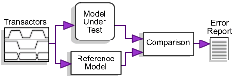
Using a transaction manager queue to mix transaction streamsFor simple test sequences, you can execute a series of transactors from a single process, one after the other. If you want multiple transactors to execute at the same time, then you can use non-blocking calls to the transactors. But, if you want to have multiple sequences of transactions running in parallel, then you must develop a more involved transaction sequencer. One solution is to create a process for each sequence of transactions that you want to run in parallel. But, this is limiting in situations where you need to have control over all the types of transactions to run in one process. For example, in order to fully exercise an ATM switch, you need to send ATM cells to each input port simultaneously. Also, randomly determining the port number and ATM cell data to transmit can enhance the test bench. So, it would be nice to be able to generate X number of cells to send and transmit them to the switch through random port numbers. And while doing this, not allowing one particular transmitter to block another. So, a second solution is to create a transaction manager that reads transactions from a queue and executes them one after the other. You could have one transaction manager instance per port and place transactor calls randomly into their queues. In Verilog, this is difficult to do and beyond the scope of this paper so we are just going to cover how to implement this solution in VHDL and C++. In VHDL, you can implement a transaction manager by using the "hierarchical referencing" technique above and by creating the following: 1) an additional record type, TApplyCall that stores a Transactor Node and the transactor's parameters, 2) a queue of TApplyCall's, 3) functions that can be used to place TApplyCall's on the queue, and 4) a process that will read TApplyCall's from the queue and use them to execute a transactor. The transactor parameters can be represented using a "line" in VHDL so that TApplyCall can be used for all types of transactors. Then, you would add a data member to the Transactor Node that represents the type of the transactor that the transactor manager can switch on to determine what method to call to run the transactor. That method would be responsible for extracting the appropriate parameters from the parameters "line" and executing the transactor using the control signal index as described in the " hierarchical referencing" section. In C++, a class can be written to represent the transaction manager. This class would read transactors from a queue and call a virtual method, Execute, to run the transactor. So, there would be a base class that all transactor classes derive from and each transactor class would have it's own data member to represent the parameters to use for a particular transaction. Each transactor class would be responsible for actually performing a particular bus transaction when the Execute method is called (i.e. by using TestBuilder, SCV, or PLI). For each transactor that you want to place in the queue, you would create a new instance of the transactor class, set up its parameters data member and push it onto the queue. Using a golden reference model to verify design output in the face of randomized inputA golden reference model is an unclocked, behavioral model of the system design that can be used to verify the output of a low level model (either RTL or gate level). The golden reference model must model both the design under test and the functionality of the surrounding BFMs. The same transactions are applied to both the lower level model under test and the golden reference model and the outputs of the two models are compared to ensure that the lower level model is functioning properly. By using a golden model, a verification engineer can avoid having to manually determine the expected results of his directed tests. Further, the use of a golden reference model is virtually required when performing constrained random tests as it would take too long to manually determine expected results for a large number of randomly generated transactions. The figure below shows a typical structure for a testbench that uses a golden reference model to verify the output from the design model.
When written in C++, golden reference models usually consist of several classes, one for each type of device in the system. Each class contains functions for each type of transaction that the device participates in. These functions take their inputs and compute the appropriate outputs in zero simulation time since the functions are all untimed behavioral code. The code for the golden reference model is also much simpler than the code for the RTL-level model as it doesn't need to account for low level protocol details such as when data becomes available during a transaction or handshaking requirements of a transaction. The outputs from the golden reference model can be generated before, during, or after the testing of the design under test. There is one advantage to running the golden reference model and the simulation model in parallel: the randomization of the transactions and transaction data can be modified at runtime according to coverage requirements of the test bench. However, this approach does require that the output values for both models be available at the same time during the test bench so that the values can be compared. This can be achieved by calling the appropriate golden reference model function at the end of the execution of a transactor when the results from the lower level model become available. Since the golden reference model is an untimed model, its outputs are available immediately after the function call is made and the results of the two models can be compared. ConclusionTransaction-based BFMs enable very robust, reusable testbenches to be created, but some problems occur when writing these type of testbenches due to limitations in VHDL and Verilog. In this paper, we have examined several coding techniques for overcoming these problems as well as some ways to overcome them using a combination of C++ and Verilog or VHDL. SynaptiCAD makes a graphical bus-functional model generator called TestBencher Pro that will generate the code described in this paper. Daniel Notestein, co-founder of SynaptiCAD, is the chief architect for SynaptiCAD's WaveFormer Pro and VeriLogger Pro products. Notestein obtained his bachelor's degree in electrical engineering and minors in computer science and math from Virginia Tech and his MSEE from the University of Texas. Ben Rhodes is the project leader for SynaptiCAD's TestBencher Pro product. His areas of special expertise include VHDL, Verilog, SystemC, OpenVera, and e test bench coding. Rhodes obtained his BSEE from Virginia Tech. |
|
|