|
|||||||||||||||||||||||||||||||||||||||||||||||||||||||||||||||||||||||||||||||||||||||||||||||||||||||||
|
|
Test Bench Generation from Timing Diagramsby Donna MitchellAppendix D to VHDL Made Easy by David Pellerin 1996 IntroductionSurveys of VHDL users have indicated that generation of VHDL test benches typically consumes 35% of the entire front-end ASIC design cycle. It is clear that automation of test bench generation would significantly reduce the costs of VHDL-based design. This section describes a method for automating the generation of VHDL test benches using a combination of graphical and equation-based methods. Background: What is a Test Bench?After a VHDL model is written, it must be tested to verify correct operation. To do this, the designer provides the simulator with a set of input signal transitions (stimulus vectors) to exercise the circuit. These stimulus vectors are usually grouped together in an entity called a test bench. Grouping the stimulus vectors together in an isolated entity provides a means to reuse the stimulus vectors as the VHDL code for the circuit changes (e.g. as the simulation models are changed behavioral models to structural models). In VHDL there are two ways to write stimulus vectors: using wait statements or using transport statements. Transport-based test benches are smaller and easier to read than wait-based test benches, but wait-based test benches are easier to understand when single-stepping through a simulation to debug it. Figure 1 shows examples of both wait-based and transport-based test benches.
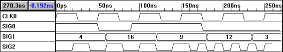
Figure 1: VHDL test benches Writing a VHDL test bench is one of the most tedious and error prone parts of the simulation process. In VHDL you are required to specify the time for each signal transition. It is easy to make mistakes when writing an HDL test bench, because it is difficult to visualize the temporal relationships between transitions on different waveforms. For instance, take a look at the transfer statements in fig. 1 and see if you can figure out if the first rising edge of SIG0 comes before the rising edge of the third cycle of clock clk. This is where a graphical timing diagram editor like The WaveFormer excels. Figure 2 shows a timing diagram that generated the code in Figure 1. Looking at the timing diagram, it is easy to see that the SIG0 transition does occur before the rising edge of the clock.
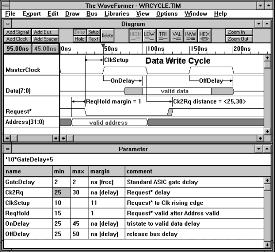
Figure 2: Timing diagram that generated the code of Figure 1 Automating Test Bench Generation using The WaveFormerThe WaveFormer is a timing diagram editor with the ability to generate and translate stimulus vectors to a variety of different simulation and documentation formats (including HDL test bench formats). Although specialized tools for translating stimulus vectors have existed for several years, these tools have traditionally been high-priced niche products that don’t offer the sophisticated timing analysis and documentation features of timing diagram editors. Timing diagram editors such as The WaveFormer allow users to interactively perform timing analysis on their waveforms and document timing relationships using delays, setups, holds, and textual information. These features along with the ability to generate test benches and import results from simulations and test equipment makes The WaveFormer the ideal environment for waveform manipulation and analysis.
Figure 3: Picture of The WaveFormer Tutorial: Generating VHDL Test Benches with The WaveFormerIn this tutorial we will demonstrate how to use The WaveFormer to generate VHDL test benches. You can perform the tutorial using The WaveFormer evaluation version located on the CD ROM at the back of this book. If you are running Windows 3.1 then you will also have to install the Win32s libraries which are also located on the CD ROM (Windows 95 & NT users do not need the Win32s libraries). A SunOS UNIX evaluation version can also be downloaded from SynaptiCAD’s web site at http://www.syncad.com/. Figure 2 is the completed tutorial timing diagram. Automatically generate a clock signal using The WaveFormer The WaveFormer supports automatic generation of periodic signals (e.g. a 66MHz clock with a 40% duty cycle). To create a periodic waveform, the user enters information about the clock such as frequency and duty cycle and The WaveFormer generates an appropriate waveform. We begin the tutorial by creating a clock named "clk0" with a period of 50ns (20mhz).
Although we only used a value to set the period of this clock, clock attributes can also be based on formulas. Clock formulas can be defined in terms of timing parameters and the attributes of other clocks. For more information on clock parameters, read the on-line help Table of Contents/Design Function Index/Clocks entry. Your clock should look like the clock in figure 2. If you made a mistake designing the clock, double left click on a clock segment to reopen the "Edit Clock Parameters" dialog box. Double left clicking on a clock edge opens up the "Edge Properties" dialog box which displays the edge time. Draw signals in The WaveFormer Next we will draw signals SIG0 and SIG1.
If you made a mistake drawing the waveforms, use the following editing techniques to correct the waveform: 1) drag and drop signal edges, 2) select a segment then click a new state button to change the state of the segment, 3) select an edge, a segment, or a signal name and hit the delete key to delete the selected object, 4) double click on an edge or signal name to edit it, 5) double click on a segment to insert a new segment. Generate Signals using Waveform Equations If a waveform has a periodic or known pattern, then it is easier to specify the signal as an equation rather than drawing each repetitive piece of the signal. The WaveFormer has an equation interface for just those types of signals. For example, SIG2 is a periodic waveform with a change in frequency from 25Mhz to 50Mhz which is generated from the following temporal equation:
SIG2 (20ns=0 20ns=1)*4 (10ns=0 10ns=1)*5
If a signal named SIG2 already existed when this equation was entered, this waveform would be added on to the end of the signal. This ability to concatenate waveforms to an existing signal in combination with the scripting language of The WaveFormer (discussed further in the import/export section) makes it possible to create extremely complex waveforms. Advanced data types: Extended State Information and Object Properties The WaveFormer supports both simple std_logic signals and complex user-defined data types for VHDL test benches. By default all signals are assumed to have a type of std_logic and a direction of out (CLK0, SIG0, and SIG2 will use the defaults for this tutorial). To model complex data types and user defined states, The WaveFormer has object properties and extended state features which allow the user to attach arbitrary data to objects in the timing diagram. This means that The WaveFormer can support all VHDL data types including arrays and user-defined enumerated types. To demonstrate the object properties and extended state features, we will add information to SIG1 so that it is exported as a VHDL signal with a type of integer, and each state in SIG1 will have an integer value.
Note: The type and state values of SIG1 could be anything that the user desired. For example the VHDLtype could be MYCOLOR and extended state information could be RED, BLUE, BRIGHT BLUE, GREEN, and PURPLE. Export to VHDL Next export the timing diagram to a VHDL test bench. To export the timing diagram to VHDL:
The generated file should look approximately like the file displayed in Figure 1 (because of drawing differences the times for signal transitions may differ slightly). Customizable VHDL output using Waveperl Scripting Language The WaveFormer uses a scripting language based on Perl (Practical Extraction and Report Language) to import and export waveform stimulus. The use of a scripting language means users can modify the output of existing translation scripts and even create their own scripts to support waveform formats used by custom test equipment and internally developed software.
We are adding new scripts all the time so send us an email at Sales Office and tell us what import/export formats that you would like us to add. Also all the scripts that ship with The WaveFormer are editable by the user. This is particularly useful because most waveform timing information is written in only a couple of different formats. So most likely if you have a proprietary format then there is probably a Waveperl script that does most of what you need done. Waveperl scripts are normal text files that can be edited with any text editor. Beyond Simple Stimulus Generation: In this tutorial we have a demonstrated how to create a simple timing diagram using drawn and equation-generated signals and clocks, and how to generate a VHDL test bench from this diagram. We have not demonstrated the timing analysis features of The WaveFormer such as min/max delay path calculations, setup and hold checking, timing parameter equations, reconvergent fanout calculation, and library generation. These features are covered in the on-line tutorials and examples that ship with the evaluation version. |
||
|
|