Analog Waveform Viewing and SPICE support
SynaptiCAD's timing diagram editors and waveform viewers allow analog
signals to be displayed, imported, created, and
manipulated. WaveFormer Pro and DataSheet Pro also support exporting to SPICE. Digital signals can be converted to
analog signals and vice versa (similar to the way
analog-to-digital converters operate). There is also
a tutorial called Creating Analog Waveforms that
will help you work through some of the features.
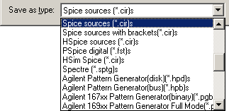
SPICE Export
Spice Export is only available in WaveFormer Pro and DataSheet Pro, unlike analog waveform display which
is supported by all of our timing diagram editor products.
Analog Display
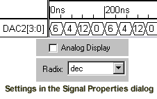
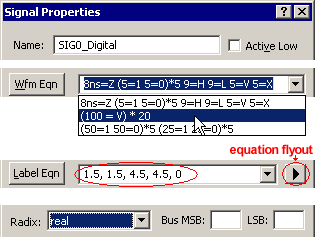
Signals store analog data as digital valid segments with real floating point values.
By checking the "Analog display" box in the Singal Properties dialog, the signal will display as an analog magnitude plot.
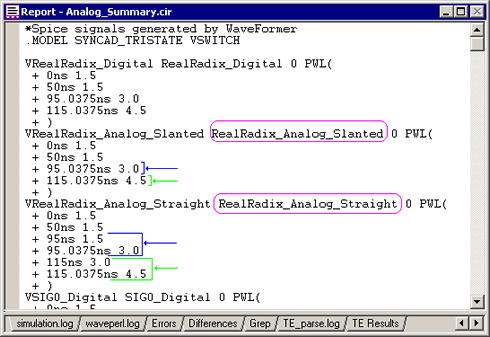
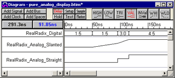
The three signals in the diagram
below have the same waveform values. Signal
RealRadix_Digital is displayed as a digital
waveform. The bottom two signals have their Analog
Display checkboxes checked, so they draw as
magnitude plots instead of as bus values. The second signal,
RealRadix_AnalogSlanted, shows the waveform using
the analog values of each segment drawn from point
to point (piecewise-linear). The third signal,
RealRadix_AnalogStraight, shows the waveform using
the analog values of each segment drawn as step
voltages. The setting for straight edges is located in the Analog Properties dialog.
Draw Analog Waveforms
Analog signals can be created by
drawing valid segments and inserting floating-point
or hexadecimal values for the segment states.
However, most analog signals require a lot more data
points than can be realistically drawn and entered
by hand. One way to generate the signals is to use
Waveform and Label equations.

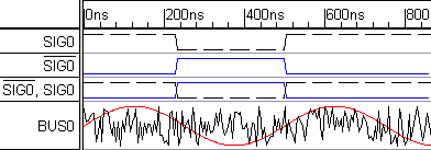
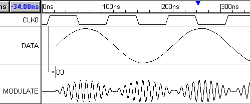
The timing diagram editors and veiwers can display differential
(or superimposed) analog and digital signals. Each signal has a setting for color, line type (solid, dashes, ...),
and line thickness so you can easily show the differences between the signals.
Individually customize signal height to scale analog waveforms.
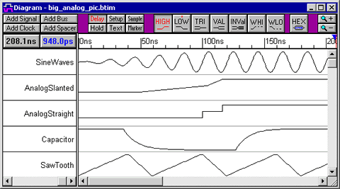
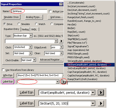
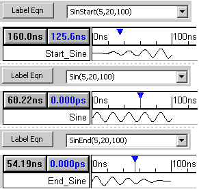
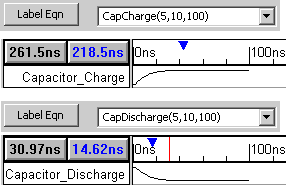
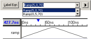
Sine Waves, Capicators Waveforms, and Ramps
Label Equations can be used to generate Sine wave
signals, capcitor charging and discharging waveforms, and ramps. Just pick an equation from the equation flyout then replace the
parameters with your values and the waveform will be automatically generated.
Import Analog Waveforms
- Import analog data from SPICE simulations, digital oscilloscopes, Mathematica, and MATLAB!
|