|
|||||||||||||||||||||||||||||||||||||||||||||||||||||||||||||||||||||||||||||||||||||||||||||||||||||||||
|
|
Timing Analysis OptionSynatiCAD's timing analysis engine uses sophisticated algorithms to detect both timing violations and overly pessimistic assumptions about system performance. The timing analysis engine accounts for timing effects that are difficult to compute manually such as delay correlation, reconvergent fan-out, and jitter and buffering in clock trees. The timing analysis engine comes standard with WaveFormer Pro, Timing Diagrammer Pro, and DataSheet Pro. It can also be purchased as an option to upgrade the waveform editor in VeriLogger Pro, BugHunter Pro, or WaveFormer Lite.
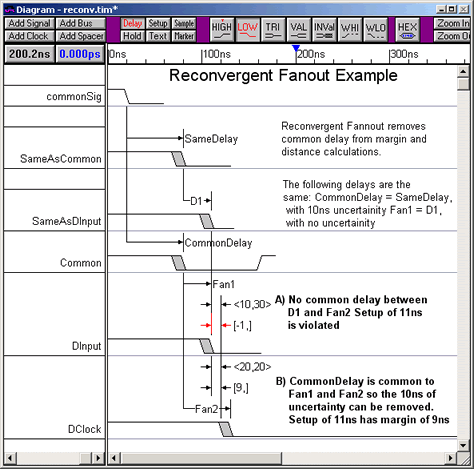
In addition, WaveFormer includes an HDL simulation engine which allows it to quickly model multi-bit register and latch circuits, along with the ability to simulate behavioral HDL code blocks, which are features that are not available in any other timing diagram editor. Reconvergent Fanout (Common Delay Removal)SynaptiCAD's timing diagram editors automatically remove common delays from margin and distance calculations by using an exhaustive multi-path timing analysis algorithm. Common delay removal happens in timing paths which share a common transition early in the circuit, diverge through different circuit paths, and then "re-converge" at the inputs to a device. When two timing paths share a common transition, the uncertainty of that transition should not affect distance and margin constraints between transitions further down on the timing paths. This is because the common transition occurs at the same time for both timing paths. (It does not matter where in the uncertainty region the transition occurs because it is the exact same time for both timing paths). This effect is called reconvergent fanout because it usually occurs when a signal fans out to multiple gates and the outputs of these gates reconverge as inputs to a common gate. If the effects of reconvergent fanout were ignored, a good design might seem to violate a timing parameter because the margin calculations were overly pessimistic.
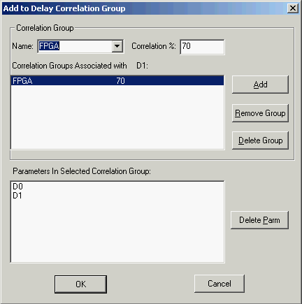
The timing diagram editor automatically accounts for reconvergent fanout effects, correctly calculating margins and distances for parameters. Reconvergent fanout does not change the uncertainties of individual transitions so they are not visible on the timing diagram itself (except for constraint margins and distance values). Example: In the above example, a NAND gate has an uncertainty region of 10ns and is represented by CommonDelay. The NAND output fans out to two signal paths, Fan1 and Fan2, that go through some gates and reconverge at the data and clock inputs of a D Flip-Flop. The difference in arrival times of the two paths should just be the delay and uncertainties of the two paths. The 10ns uncertainty of the NAND gate should not affect the difference in arrival times because both signals will start at the same time (somewhere in the uncertainty region of the NAND gate). So the setup time for the CommonDelay path is satisfied. The SameDelay to D1 path, has the same timing as the CommonDelay to Fan1 path, however since SameDelay could occur at any time during its uncertainity region regardless of where CommonDelay triggers, the 10ns can not be removed in this case. The setup time for the SameDelay path fails. Delay CorrelationSynaptiCAD's timing diagram editors support delay correlation for all delays and clock buffer delays within a timing diagram. Delay correlation is a method of relating two or more delays that are found within the same IC. This relationship accounts for the likelihood that if one of these delays falls at the high or low end of its tolerance, the other delay(s) will as well. The successful use of this information can allow circuits to be designed that run at higher clock speeds. It can also help to prevent timing violations. Delay correlation is particularly useful for speeding up FPGA and ASIC designs. The uncertainty regions for an FPGA or ASIC must be broad enough to account for IC process variations in chips that are produced in different lots. However the actual skew between delays on the same chip have a much smaller divergence then is specified in the chip's data sheet. With SynaptiCAD's delay correlation feature you can create groups of delays who's uncertainties will vary by a defined percentage. For example if the correlation is 100% then all delay uncertainty is removed. If Correlation is 0% then no delay uncertainty is removed. If Correlation is 50% then half of the delay uncertainty is removed. The timing diagrams are still entered with the entire data sheet uncertainty region, and delay correlation automatically adjusts margin and distance calculations to account for these effects.
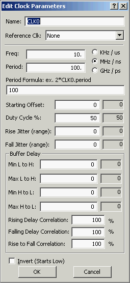
Delay correlation like Reconvergent Fanout adjusts the margin and distance calculations so that circuit timing can be optimized. The main difference is that reconvergent fanout removes 100% of common delay, where as delay correlation can remove a percentage of uncertainty from different delays in the converging paths. Delay correlation is extremely powerful because it can model the timing effects of on-chip delays. SynaptiCAD's timing diagram editors allows you to analyze virtually any combination of delays using correlation. Delay correlation effects are computed any time you place a setup, hold, or distance calculation in your timing diagram. The timing diagram editor will first verify that delays exist on either end of the setup or hold distance calculation and then perform the calculation that uses delay correlation. Clock Timing EffectsSynaptiCAD's timing diagram editors support Clocks, Sub-clocks, and Clocks with formulas, which allow you to accurately model derived clocks and clocks that have jitter and buffer delay parameters. Regular clocks are special repetitive signals that draw themselves based on their attributes: period, frequency, duty cycle, edge jitter, offset, and other parameters. Clocks can be related to other clocks by using the Reference Clock Property or by using formulas that reference another clock's attributes like period, offset, and jitter. SynaptiCAD models two types of clock timing effects: jitter and clock buffer delay. Both of these effects add uncertainty to the clock edges but they are handled differently by the reconvergent fanout and delay correlation calculators.
Jitter models the effects of random crystal oscillations from a clock generator circuit. Jitter shows the uncertainty region around where a perfect clock edge would appear. Therefore, clock jitter effects can not be removed by reconvergent fanout calculations or included in a delay correlation group. Since the whole point of modeling clock jitter is to model the worst possible behavior of the clock oscillator, this is the correct way to perform the calculations. Clock buffer delay models the effects of sticking a buffer between the clock source and the rest of the circuit. Clock buffer delay is treated like a regular delay placed from a perfect clock to a regular signal. The advantage of using the Clock buffer delay is that the user does not have draw the output clock and setup all the delays between the signals. Clock buffer delays are removed by the reconvergent fanout calculator. Also the clock buffer delay has a delay correlation group already defined and setup in the Clock dialog. By default the correlation factor is 100% so all delay is removed. But any percentage between 0 and 100 can be added to the correlation group. |
|
|