|
|||||||||||||||||||||||||||||||||||||||||||||||||||||||||||||||||||||||||||||||||||||||||||||||||||||||||
|
|
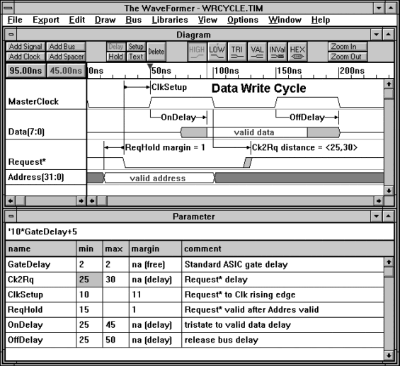
A Tutorial for The WaveFormer: a timing diagram editor and digital stimulus generatorby Donna MitchellPublished in Design Wave Magazine Vol.3 1996 in Japanese, CQ Publishing The WaveFormer v2.5SynaptiCAD has recently released The WaveFormer as an extension to its line of popular, low-cost EDA tools. The WaveFormer is a timing diagram editor and a digital stimulus generator. Timing diagram editors are relatively new EDA tools used to create and analyze digital and mechanical timing diagrams. Digital stimulus generators import, export, and translate digital waveform stimulus to drive simulators and test equipment. By combining these functions into a single product, The WaveFormer creates an integrated environment for creating, analyzing, and documenting digital waveform information that can be output in virtually any format (bitmap graphics, encapsulated postscript, Verilog, VHDL, Spice, and even in-house formats using user-written translation scripts). Why use a timing diagram editor?
With a timing diagram, the cause-effect relationships between signal transitions are shown by timing
parameters like delays, setups, and holds. Even when engineers have access to digital simulators they
still need to draw timing diagrams to help clarify the operation of critical sections of a design.
Figure 1: Picture of The WaveFormer. Stimulus editing capabilities adds interoperability with other tools
The WaveFormer can be used as a stand-alone design verification tool or in conjunction with a digital
simulator. All simulators need input stimulus to perform a simulation. The WaveFormer makes it easy
to generate digital stimulus either graphically or textually and view the resulting stimulus without
having to simulate it first. In addition, The WaveFormer supports the import of waveforms from other
tools, so it can serve as a translator between different waveform formats.
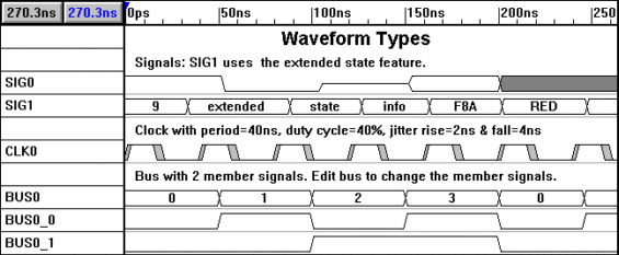
Tutorial on Timing Diagram Editing Features:The following sections introduce the basic timing diagram editing capabilities of The WaveFormer such as drawing and generating waveforms, attaching timing parameters to signal transitions, and analysis of the resulting diagram. If you would like you can follow along using The WaveFormer evaluation version included on the CD ROM at the back of this magazine. The evaluation version also includes a complete, on-line version of The WaveFormer manual and two tutorials (basic and advanced). Drawing Waveforms The WaveFormer can graphically generate signals, buses, and clocks. Figure 2 shows the three different types of waveforms. Each type of waveform is added by clicking the appropriate ADD button in the upper left corner of the diagram window.
Figure 2: Signals, Clocks and Buses are three types of waveforms that can be generated by The WaveFormer.
Signals are waveforms that represent a single digital input or output. Signals are drawn by pointing
and clicking the mouse inside the diagram window. The logic state of the waveform segment that is drawn
is determined by the state buttons (HI, LO, TRI, VALID, INV). The state buttons automatically toggle
between the last two states drawn, making it easy to quickly create a new waveform (the toggle action
can be turned off by clicking twice on the same state button). To change the state of an existing waveform
segment, click on the segment and press the desired state button. To move a signal transition, click
on the transition and drag it to the desired location. To delete signals, select the desired signal
names and press the delete key.
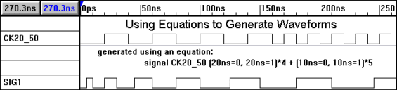
Using Equations to Generate Waveforms
Some signals are easier to create using a temporal equation instead of drawing them. For example, a
change in frequency in a periodic waveform from 25Mhz to 50Mhz could be represented by the following
temporal equation:
for ($i = 0;$i < 10; $i++)
{
  $time = 5 * $i;
  wfm SIG1 $time=0 $time=1;
}
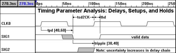
Signals generated using temporal equations are treated the same as signals drawn by hand (edges can be moved and states can be changed using the normal drawing features). Timing Parameter Analysis: Delays, Setups, and Holds The true power of a timing diagram editor comes from the ability to relate different signal transitions through timing parameters. Delays, setups, and holds are the three basic types of timing parameters (see Figure 4). Other commonly used timing parameter types such as pulse width requirements can also be modeled using these three basic types.
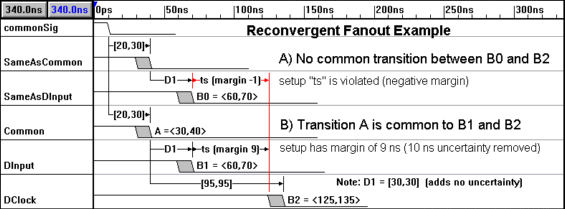
Figure 4: Timing Parameter Analysis: Delays force signal transitions to be a specified distance. Setups and Holds verify that distances between signal transitions meet timing requirements. A delay between two signal transitions will force the transitions to be a specified distance in time from each other. This keeps the designer from having to manually place signal transitions at exact times. For example, to make two signal transitions exactly 15ns apart: roughly sketch the waveforms and add a delay parameter between two signal transitions using the right mouse button. Next type 15 into the min or max column of the delay in the spreadsheet. The second signal will move so that it is exactly 15 ns from the first signal transition. Now that the two signal transitions are related, if either is moved then the other will follow in order to keep the correct timing. This is how changes in timing are propagated through the diagram. Setups and holds are timing requirements that must be met by a design in order for the system to function properly. A setup time monitors a transition on a data signal before a control signal transition (e.g. system clock transition). A hold monitors a transition on a data signal after a control signal transition. The distance between the control and data transitions minus the hold or setup time is the safety margin or margin of the timing parameter. The WaveFormer automatically calculates the margin times for setups and holds and displays them in the parameter spreadsheet so that the designer can determine how much further the timing of the circuit can be adjusted. If a timing change causes a setup or hold time to be violated, the margin of the violated setup or hold will be shown in red. All margins are recalculated whenever there is a timing change. This automatic recalculation of timing requirements makes it easy for designers to weigh the tradeoffs of different design choices. Reconvergent Fanout Margin calculations in some circuits can be overly pessimistic if all the uncertainty times in a timing path are included in the calculations. For instance, if two signal transitions B1 and B2 are caused by the same transition A (see Figure 5), then margin calculations between B1 and B2 should not include the uncertainty of transition A, because no matter when A transitions it will occur at the same time for both B1 and B2. When this happens the circuit is said to have reconvergent fanout, because this typically occurs when two signals diverge (fanout) from a common source and reconverge at the inputs of a gate. The adjustment of timing calculations to account for reconvergent fanout is referred to as common delay removal, because the uncertainty created by delays common to both timing paths is removed. The WaveFormer.s ability to recognize and remove the pessimistic effects of reconvergent fanout is especially important for circuits with demanding timing requirements. Performing common delay removal on manually drawn timing diagrams is tedious and error prone, but ignoring this effect can lead to sub-optimal designs.
Figure 5: Demonstration of reconvergent fanout example. Short Tutorial on Stimulus Generator.The WaveFormer can input or export digital waveform information to VHDL, Verilog, Spice, and even in-house formats using user-generated translation scripts. To demonstrate the exporting features we will use the .VHDL transport. script in which signal transitions are implemented using a signal assignment state for each signal. This script produces a complete entity-architecture test bench that can be directly compiled and linked into a VHDL simulation. VHDL Export Example To model complex data types and user defined types, the VHDL script takes advantage of the object properties and extended state features of The WaveFormer. These features allow the user to attach arbitrary data to objects in the timing diagram which can then be accessed by the Waveperl scripts. The VHDL script recognizes two different properties which can be manipulated through the Export\Edit Object Properties menu. The properties are:
      property = VHDLdir    default value = out
      property = VHDLtype   default value = std_logic
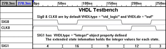
Figure 5 shows a timing diagram and the resulting VHDL code that was generated by The WaveFormer. Sig1 is exported to VHDL as a signal of type integer with numerical values for its various states. To get Sig 1 to be type integer we attached the object property of VHDLtype=integer to the signal. To change the object properties of Sig1:
To add the extended state information to Sig1 so that segments can have values like 7 and 8:
To export the timing diagram to VHDL:
Figure 6a: Simple timing diagram to be converted to VHDL Code
library ieee, std;
use std.textio.all;
use ieee.std_logic_1164.all;

entity testbench is
  port(
      SIG0		: out std_logic;
      CLK0		: out std_logic;
      SIG1		: out integer
      );
end testbench;

architecture test of testbench is
begin

  process
  begin
    CLK0 <= '1';
    wait for 0 ps;
    while true loop
      CLK0 <= '0';
      wait for 50000 ps;
      CLK0 <= '1';
      wait for 50000 ps;
    end loop;
  end process;

  process
  begin
    SIG0 <=
    	transport '1' after 0 ps,
    	transport '0' after 50000 ps,
    	transport '1' after 90000 ps,
    	transport '0' after 180000 ps,
    	transport '1' after 240000 ps;
    SIG1 <=
    	transport  4 after 0 ps,
    	transport 16 after 60000 ps,
    	transport  9 after 120000 ps,
    	transport 12 after 185000 ps,
    	transport  3 after 238000 ps;
  end process;

end test;
Figure 6b: VHDL code generated by The WaveFormer. Writing your own scripts
Waveperl is an extended version of the Perl language that contains additional functions for creating
and manipulating data structures inside The WaveFormer (TWF). Waveperl scripts are compiled (dynamically
whenever the script is run) and executed by a perl interpreter embedded into TWF. Waveperl scripts are
primarily intended to be used for waveform import/export operations, but users can also write scripts
to add new editing functions to The WaveFormer.
SummaryThe WaveFormer can be used throughout the design cycle. As a system specification and analysis tool, The WaveFormer is particularly useful for pre-schematic analysis before simulation is possible. During the design phase The WaveFormer serves in a dual role as timing analyzer and testbench generator for simulations. As a documentation tool, The WaveFormer allows the generation of detailed timing diagrams that are vastly easier to create and maintain than those that can be generated using conventional drawing packages. One of the most pleasant benefits of using The WaveFormer is that circuit documentation can be generated automatically as a by-product of the design process. The low cost of The WaveFormer makes it possible for companies to standardize on timing analyzers as a method for storing maintainable on-line timing documentation. Site licenses are available at significant discounts that bring The WaveFormer into the same price range as word processors and spreadsheets, making it likely that The WaveFormer will be used not only by design engineers, but also by marketing, test, maintenance, and applications engineers. |
|
|