|
|||||||||||||||||||||||||||||||||||||||||||||||||||||||||||||||||||||||||||||||||||||||||||||||||||||||||
|
|
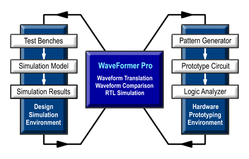
Fusing Hardware and Simulation Test Bench Developmentwith Virtual Prototyping Techniques Designers are looking for new methods to reduce verification time for both simulation models and hardware prototypes. In many ways both of these environments suffer from the same problems of test vector creation, test coverage, analysis of results, and detection of elusive timing problems. There are many EDA tools and hardware test systems available to help solve these problems in each environment, but in the past there has not been a way to leverage the work done in one environment into the other. In this paper, we propose several techniques that unite the worlds of simulation and hardware verification and which take advantage of strengths offer by each environment. 2.0 Basic Virtual Prototyping SetupOur proposed solution uses a technique called virtual prototyping, which employs a combination of pattern generators, logic analyzers, and EDA software. Figure 1 shows the basic virtual prototyping setup. SynaptiCAD offers products that can act as two way waveform translators between the simulation and hardware environments and provide an analysis platform for comparing and measuring the results. Virtual prototyping techniques are divided into two categories: EDA-assisted hardware verification and Hardware-assisted simulation verification.
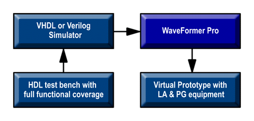
Figure 1: Virtual Prototyping Setup 3.0 EDA-Assisted Hardware VerificationIn the following virtual prototyping setups, we will show several ways to leverage the work done during the design phase of the product to simplify the development of a hardware test environment. These include: using waveform data from the simulation phase to generate pattern generator stimulus, comparing captured waveform results against simulated results to detect hardware errors, and using the simulation environment to help troubleshoot detected errors. 3.1 Generating Stimulus for Pattern Generators Programming a pattern generator with enough stimulus to adequately exercise a hardware prototype has traditionally been a very labor intensive and error prone process. SynaptiCAD's WaveFormer Pro eliminates this problem by allowing the reuse of waveforms from the simulation phase to serve as the waveform stimulus. In addition to direct translation, WaveFormer can generate stimulus waveforms using a combination of graphically drawn signals, timing parameters that constrain waveform edges, clock signals, and temporal and Boolean equations for describing complex, quasi-repetitive signal behavior. Advanced operations on signals such as time scaling and shifting, and block copy and pasting of signal behavior over an interval of time are also supported. This simple, but powerful environment dramatically eases the labor associate with the generation of complex stimulus. The resulting hardware test benches also have the same functional coverage of the simulation models ensuring that the hardware prototype is adequately tested. Figure 2 shows the design flow for the test bench conversion.
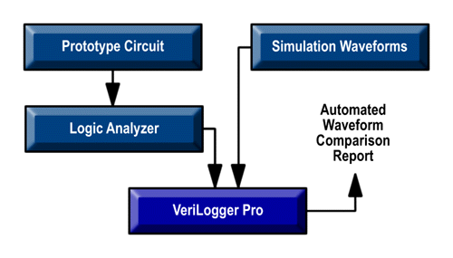
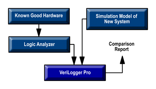
Figure 2: Creating Stimulus Vectors for a Pattern Generator 3.1 Verifying Hardware Response with Simulation Compare Traditionally, waveform data from a logic analyzer has required visual inspection by an engineer familiar with the operation of the circuit to verify proper operation or to troubleshoot an error. As the number of waveforms and the amount of data captured increases manual inspection is no longer feasible due to the sheer amount of data that must be analyzed. SynaptiCAD's VeriLogger Pro software overcomes this problem by providing a set of automated comparison functions with the ability to compare logic analyzer data to simulation results as shown in Figure 3. Automated comparison guarantees a rigorous check of each data point, ensuring the detection of "small impact" errors that are easily missed during visual inspection of the waveforms. Another important advantage of automated verification is it reduces the amount of knowledge required by the verification engineer to test the system. Rarely does even the designer of a system keep a detailed vision of the operation of all the signals in his design (that's the reason for simulators), yet that is exactly the capability needed to spot a hardware error. The simulation environment, however, knows exactly how the signals should be acting, so it is the ideal tool for identifying any differences between the actual response and the correct response.
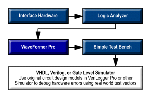
Figure 3: Verifying Hardware Response using the Simulation Results 3.3 Simulate and Visualize Acitivity on Internal Nodes One of the most frustrating problems encountered when debugging a circuit is the inability to see what is happening on all the internal signal nodes of an FPGA or ASIC. A logic analyzer can only show the activity on signals that are brought out on device pins. Unfortunately, many designs are I/O limited. Even when there are no limitations, there are almost never enough pins available to bring out all the useful nodes. To combat this problem, WaveFormer Pro contains a built-in interactive simulation engine that can simulate registered logic equations like those used in FPGAs or CPLDs. Engineers can quickly generate internal signals to check specific points. If a broader view is needed, then WaveFormer can generate a VHDL, Verilog, SPICE or gate-level stimulus file which can be simulated with the original design models to view the entire circuit operation. 3.4 Find Elusive Setup and Hold Violations Another benefit of combining a simulation environment with a hardware prototyping setup is the ability to generate complex timing analysis reports. For example, the simulation environment can generate a report of ALL setup and hold timing violations specified between any two signals in a timing diagram regardless of whether this signal is a captured waveform or a simulated waveform (logic analyzers typically only flag the first violation). Setup and hold time violations in ASICs and PLDs are particularly troublesome because the timing violations usually occur on flip-flop inputs that are not directly available at device pins, but are instead a logical function of the device's inputs. Using conventional debugging techniques, these timing violations are extremely difficult to catch because they cannot be directly measured. Using a simulator, we can determine the response of the internal signals, simplifying the detection of timing violations between signals buried inside the chip. 4.0 Hardware Assisted HDL Simulation VerificationJust as design data can be transferred into the test domain to help verify hardware, the reverse process can also be successfully applied to the design and simulation of new systems. Most systems being designed need to interface with already existing hardware (IC's or entire boards) and simulation models are frequently not available for that hardware. Waveforms from the existing hardware can be captured with a logic analyzer and converted to HDL test bench code or SPICE stimulus and used to test the new system. Existing hardware can also be use to verify that a next-generation system's interface is compatible with the older hardware. 4.1 Generating Stimulus for Simulation Environment In Figure 4, we use the logic analyzer to capture the raw waveforms from an existing hardware system and convert that data into a VHDL or Verilog test bench. This method is particularly effective for testing FPGA's and ASIC's which interface to existing systems. Instead of spending weeks developing a test bench the engineer can capture real world stimulus and begin testing within minutes of capturing the data. WaveFormer's built-in timing diagram editor can also scale and manipulate the captured waveforms. For example, assume a set of waveform data was captured from a current generation system running at 50Mhz and the new (not yet completed) system will run at 90Mhz. The captured waveforms can be scaled to the higher speed and then used to test the new system's simulation models.
Figure 4: Use Existing Hardware to generate stimulus models for a new simulation model 4.2 Interface Functional Testing Often the system being designed is the next generation of an existing product with similar functionality. In this case, the new system must generally mimic at least part of the interface of the older system. By performing a waveform comparison between the old system and the new design, correct functioning of the new system can be assured. Figure 5 shows the design flow for this type of verification.
Figure 5: Using an existing system to test interface compatibility with a new design 5.0 SummaryBy using the techniques discussed above, engineers are able to exchange waveform data between their simulation and hard test environments. Re-use of this type of data dramatically reduces the time required for both design and hardware verification and produces more comprehensive test suites. This results in the best of both worlds: faster time-to-market for new products and reduced chance for errors after product introduction. AuthorDonna Mitchell is vice president of strategic marketing at SynaptiCAD Inc. She received her BS and MS degrees in electrical engineering from Virginia Polytechnic Institute and State University. Mitchell is one of the two founders of SynaptiCAD Inc. She co-developed SynaptiCAD's first product, a timing diagram editor called Timing Diagrammer. Mitchell's industry experience includes 14 years of hardware and software development. Prior to her work at SynaptiCAD she designed board-level mixed-signal systems at Analog Devices and Burr Brown Corporation. |
|
|