|
|||||||||||||||||||||||||||||||||||||||||||||||||||||||||||||||||||||||||||||||||||||||||||||||||||||||||
|
|
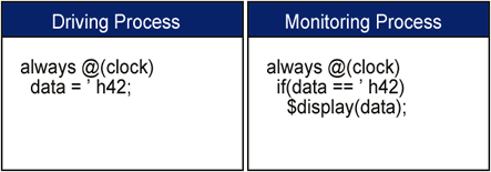
Finally, A Verification GUI!Graphical Code Generation Solves Verification Problems Verification design complexity will force many of you to reconsider your current methods of creating test benches. But the available choices are difficult to evaluate. Will you stick with a modeling language like VHDL, Verilog, or SystemC? Or will you switch to one of the new verification languages such as OpenVera or the "e" language? Whatever choice you make, you are still faced with the problem of developing complex test benches, and maintaining that code over the course of several projects and possibly several verification engineers. Graphical code generation offers a language independent solution to test bench development that enables engineers to quickly describe test benches in a manner that is clear and precise. Graphical test bench generation is the process of automatically creating test bench source code from an interface description and the bus transactions supported by the user's model. Instead of entering the test bench code by hand, the developer sends his HDL model under test to a test bench generator, which automatically extracts the port interface signals of the design into a timing diagram editing environment. This timing diagram editor is then used to create timing diagrams that describe the bus transactions for the test bench. By automating the most tedious aspects of test bench development, engineers can focus on the design and operation of the test bench rather than the painstaking aspects of code development. Advanced ModelingSynaptiCAD has developed TestBencher, a simple and intuitive graphical test bench generator that can be used to model very advanced bus transactions and interface descriptions. Pipelining, split-phase transactions, data structures and memories, and sequence recognition can all be modeled. TestBencher uses the timing diagrams to generate bus transactor source code in the user's preferred verification language. By using timing diagrams, the engineer can work at a higher level of abstraction, free from the coding details that arise solely from the choice of a particular verification language. In the following sections we will examine some of the common problems that occur during functional verification and discuss how these problems are alleviated by graphical generation of the test bench code. Race ConditionsTest benches are frequently plagued by concurrency and synchronization issues that cause race conditions and non-deterministic execution. While these issues are simple enough in theory to overcome, in reality they are extremely difficult to manage when coding by hand. One reason is that race conditions are caused by subtle design choices that cannot be automatically found in the same way that syntactical errors are. These conditions only manifest at run time. And often they are not even detectable at run time because the race conditions may "go the right way" on a particular simulator, only to fail when run on another simulator which made a different decision on the order in which to execute the theoretically parallel operations. This poses a particular problem for IP vendors who need to distribute test benches to customers using simulators from different EDA vendors. Even when running on the same simulator, these sorts of race conditions can cause problems, because it is quite possible that a future release of the same simulator may change the order in which it executes processes to enhance simulation performance, leading to a severe maintenance headache. Using a graphical code generator, circumstances that can cause race conditions are handled automatically. For example, race conditions are common in clocked functional test benches where signals are frequently driven and sampled at the same clock edge, but on different zero-time delta cycles. Figure 1 shows a simplified example of one way these races can occur. When hand coding, the engineer must be sure to write the code in such a way that the sampling occurs as the first thing that happens during each clock cycle. This is not an easy task in hardware description languages where signals frequently change state several times during a single clock cycle. However, the concurrent events that cause these race conditions are visually obvious in a timing diagram, leading to the easy avoidance of these types of race conditions.
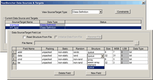
Figure 1: Simple Race Condition Constrained Random DataDuring the implementation of a hand-coded test bench it is very easy to mismatch port sizes or make other similar small errors. Automatic code generation from graphical descriptions makes it easier for an engineer to define the information in one location and use it throughout the test bench. This is especially true for creating and maintaining complex data structures that are used to supply or store state information for different transactions. A small change to a data structure often causes code changes in many different locations in the test bench. With a graphical interface, once a data structure has been defined for a project, changes to that data structure are automatically propagated throughout the test bench. The newer verification languages also support advanced data structure features such as constrained randomization of test stimulus during a simulation. With a graphical interface it is very easy to experiment with different randomization options because data structure changes are made in only one location. The example in Figure 2 shows the definition for a data structure that will provide constrained randomized data to a transaction. The fields specified for a data structure can be elements, arrays, or queues. Each field can have different properties defined, depending on the test bench language and the data type being used.
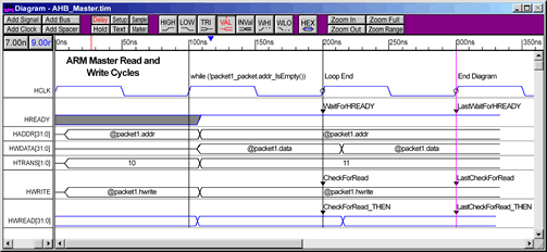
Figure 2: Complex Data Structure using Constrained Random Data TestBencher also provides the capability of easily creating complex data structures which allow data to be read from or written to a file using a spreadsheet format or can store data internally in memory. By using the memory features, data can be stored in one transaction and then used by another. Pipelined TransactionsAnother challenge in verification of designs is the implementation of pipelined bus transactions. A common need is to model some form of pipelined bus master that gets its transaction data from a queue (FIFO) of data packets. A signal state driven by the queue will cause transaction execution to pause when the queue is empty until more data is placed in the queue. Otherwise, the bus transactor will take the next value from the queue and the transaction will continue execution immediately. Figure 3 shows how a single timing diagram can be used to model both the read and write transactions of an AMBA (Advanced High-Performance Bus) master device. The AMBA bus is the main system bus for the ARM microprocessor family which supports pipelined burst reads and writes. In this example, the HADDR, HWDATA, HWRITE signals are set up to get their data from a queue called ahb which is filled by a standalone process at the top level of the test bench. Another queue is used by a sampling process callled CheckForRead_THEN to store data during a read operation. The first clock cycle in the diagram drives the HADDR and HWRITE signals. If it is a write operation, the data corresponding to that address is driven during the next clock cycle. If it is a read operation, the sampled data will be placed into a queue that can be monitored at the top-level test bench level or output to a file. There is a loop set up using markers to continue driving addresses and reading/writing data in this pipelined manner until the address queue is empty, with the address of the next read or write being transmitted at the same time as the data of the current read/write.
Figure 3: AMBA pipelined bus master driven by queue data structure
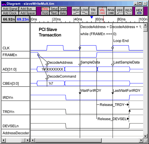
Figure 4: PCI Slave transaction implemented with Sequence Recognition Test Bench MaintenanceTest bench code is often difficult to understand even when written using modular programming techniques because of the large amount of parallel activity occurring in the test bench, much of which is distributed throughout the test bench. Timing diagrams allow a much clearer and concise description of the interaction of parallel processes and signal activity. A graphical representation also facilitates the collaboration of many engineers on a single test bench by removing the need to interpret source code. Any engineer familiar with the design specifications is able to look at a given timing diagram and have an immediate understanding of what the transactor does, dramatically simplifying test bench maintenance. SummaryGraphical automatic test bench generation provides a good solution to many of the problems faced during functional design verification. In this solution, timing diagrams are used to describe bus transactions in the test bench. Engineers are familiar with timing diagrams, so they are easily understood and the graphical representation enables the engineer to quickly visualize the test bench at a higher level of abstraction. The transactions depicted in the timing diagrams form modular components of a test bench that can quickly be modified and re-used in other designs, paving the way for faster verification of future designs. AuthorDonna Mitchell is Vice President of Strategic Marketing at SynaptiCAD Inc. She received her BS and MS degrees in electrical engineering from Virginia Tech. Mitchell is one of the two founders of SynaptiCAD Inc. She can be reached via email at Donna. |
|
|