|
|||||||||||||||||||||||||||||||||||||||||||||||||||||||||||||||||||||||||||||||||||||||||||||||||||||
|
|
WaveFormer Pro FAQ
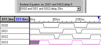
How do you design with WaveFormer Pro? WaveFormer Pro provides a graphical design environment that supports the engineer at each step in the design cycle: 1) Understanding the specification: WaveFormer Pro's graphical environment lets you start sketching waveforms and setting up cause and effect relationships as soon as you receive your project specifications. At the beginning of a project, you are generally given a set of high level timing requirements that your design must meet: interface diagrams, computational throughput, data transmission rates, response latencies to requests from external systems, etc. WaveFormer lets you manipulate and experiment with the given specifications before you attempt to design a circuit that meets the specifications. 2) Experimenting with different circuit configurations: Once you begin designing circuits to meet the timing specifications, WaveFormer Pro can start simulating your ideas incrementally, before you have even finished a complete design. WaveFormer Pro has a built-in logic wizard that will simulate Boolean and registered logic equations with true min/max timing. Changes to the design logic and stimulus automatically result in a resimulation. More complicated circuits can be described using behavioral HDL code or by calling external HDL models. WaveFormer also supports equation-based waveform descriptions (great for DSP specifications) and spreadsheet based waveforms (great for ASIC waveform compatibility). 3) Optimizing the design: WaveFormer Pro provides a what-if simulation environment that lets you switch out different manufacturer's libraries, experiment with different clock frequencies, and perform true min/max timing analysis. 4) Generate completed HDL models and professional documentation: After your circuit is completed it can be exported as a complete HDL model, as stimulus vectors to drive external simulators, and as professional quality timing diagrams for documents and data books. Back to FAQ. Why is designing with WaveFormer Pro so quick? Designers with WaveFormer Pro have two major advantages over engineers using traditional gate-level and HDL simulators. First, WaveFormer Pro works with circuits at the same level of abstraction (boolean equations, delay paths, timing requirements) as engineers do when they first start formalizing their design. This means designers can rapidly enter the essential elements of their design without having to create schematics or HDL models. The second major advantage is that unlike most EDA tools, WaveFormer Pro is interactive and gives designers feedback as they make changes to their design. The combination of these two features, rapid design entry and rapid feedback on system functionality and performance, makes WaveFormer Pro the ideal tool for the iteration intensive process of designing digital circuits and examining design tradeoffs. Back to FAQ. How are Boolean equations and registered logic equations supported in WaveFormer Pro? Boolean equations and registered logic equations are entered in the signal properties dialog box with a simple point-and-click interface. Boolean equations are an easy way to combinatorially relate one signal to other signals in the diagram. The Boolean operators and, or, nand, nor, xor, not, and delay are supported. Below is an example of an 3-input AND gate with a 20ns delay (The equation shown is for SIG3). Back to FAQ.
What if I can't describe my waveform with a Boolean equation or a registered logic equation? With WaveFormer Pro, this is not a problem. You can enter behavioral HDL code directly into WaveFormer Pro to model signals that would otherwise require many Boolean equations, or could not be represented by Boolean equations at all. Simply click on the HDL code radio button, and enter your code in the Boolean equation area. Back to FAQ. Here is an example of code that can be entered to describe a counter (direct entry of HDL code is not possible in competing products). 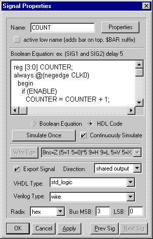
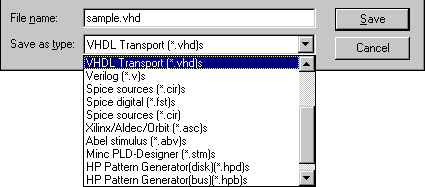
What do you mean by "Export to VHDL, Verilog, and more"? WaveFormer Pro can generate a complete HDL model from the information you enter. You can export your pre-schematic timing diagrams to Verilog, VHDL, SPICE, HP logic analyzers and many more. The exported waveforms can then be used to drive simulations.
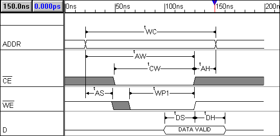
You can also import simulation results and document diagrams using delays, setups, holds, samples, markers,
and text objects. Back to FAQ.
What formats are supported for Waveform Import and Export? WaveFormer Pro currently exports digital stimulus to:
Waveform import is supported for:
What if the format I use is not currently supported? If your format is not currently supported, contact us and let us know. We are always looking to add more capabilities to WaveFormer Pro, and if we receive multiple requests for a waveform format we will try to support it. It is also possible to create your own scripts to support waveform formats used by custom test equipment and internally developed software. WaveFormer Pro uses a scripting language based on Perl (Practical Extraction and Report Language) to import and export waveform stimulus. The use of a scripting language means that you can modify the output of existing translation scripts or create your own scripts if needed. Back to FAQ. What is Instant Feedback? Instant Feedback is how we describe the interactive simulation environment found in WaveFormer Pro. Changes in your design (component models, timing information, logic equations, ect.) and input waveforms automatically force updates to simulation results, providing instant feedback on the impact of changes on system functionality and performance. Click here for an sample demonstration of the Instant Feedback capabilites. Back to FAQ. What is Realistic Databook Documentation? Exactly what it sounds like: a feature that allows text to be displayed in the same format as found in databooks. The following options are available for modifying any type of text in WaveFormer Pro: subscript, superscript, bold, italic, underline and overline. Back to FAQ.
What are the differences between WaveFormer Pro and Timing Diagrammer Pro? WaveFormer Pro contains many features not available in Timing Diagrammer Pro. WaveFormer Pro has several Advanced WaveForm Generation features such as: the ability to create and continuously simulate waveforms with Boolean equations; the ability to import waveforms from external sources including VCD files, VHDL simulator output, and data acquired from HP logic analyzers; and the ability to import raw test vectors edited in spreadsheet software (spreadsheet-based test vector generation). WaveFormer Pro contains an IEEE 1364 compliant Verilog simulation engine that supports all major constructs of the language including advanced features such as pin-to-pin timing and PLI interface routines. All the waveform translation features are also only available in WaveFormer Pro. This includes all the export formats mentioned earlier: Verilog, VHDL, SPICE, ABEL, etc. The bottom line is that if you work with simulators, WaveFormer Pro is the tool for you. Back to FAQ. Why is it helpful to graphically produce VHDL stimulus files when I can write the code myself? Writing VHDL stimulus code is one of the most annoying parts of testing a VHDL model. In VHDL you are required to specify the time for each signal transition. This is an error prone task even for relatively short simulation times. With WaveFormer, each signal transition is made with just a mouse click and you can view all the signals at the same time to see the relative time relationship of the signals (something you can’t do in most VHDL simulators until you simulate the entire circuit). What is the big difference between a timing diagram editor and other types of timing analysis tools? Timing diagrams can be drawn as soon as you have some clue as to what some of the parts for a design will be. A timing diagram is the first step to figuring out if your design works. This is different from other timing analysis tools because they require a complete circuit and models for the parts in the circuit. All the information that is necessary to draw a timing diagram is contained in data sheets which are easy to get and free unlike most simulation models. How do I get my timing diagrams into a word processor or FrameMaker?
WaveFormer supports WYSIWYG bitmaps, CGM metafiles, EMF enhanced metafiles, MIF FrameMaker files, and
EPS files. The Help\Creating Images menu command and the image.doc
file contain detailed information on exporting timing diagram images.
Do you have a question not answered here? You can email your question to Sales Office or you can call 540-953-3390 and have your question answered directly. |
|
|